Step 1
Remove 7 screws.
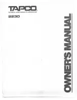
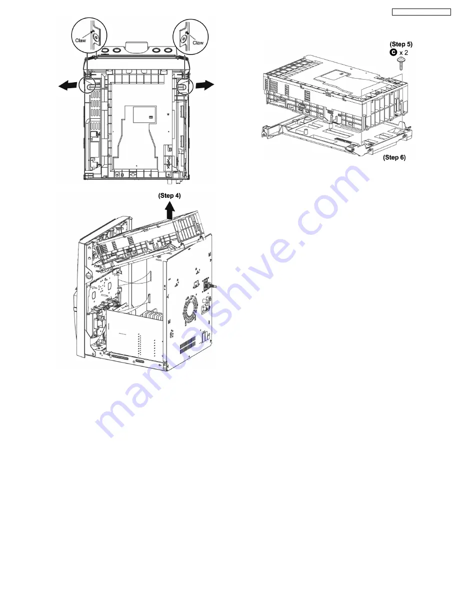
Step 4
Lift the CD changer unit upwards to remove it.
·
Disassembly of Mecha Chassis
Step 5
Remove 2 screws.
Step 6
Remove the Mecha Chassis.
Note:
For disassembly & assembly of traverse unit, please refer to
section 10.16 of this service manual.Please refer to original
Service Manual for the Disassembly and Assembly of the CD
Changer Unit (CRS1).
10.6. Disassembly of Rear Panel Block
·
Follow the (Step 1) - (Step 5) of Item 10.4
31
SA-AK750P / SA-AK750PC
Summary of Contents for SA-AK750P
Page 8: ...8 SA AK750P SA AK750PC ...
Page 13: ...13 SA AK750P SA AK750PC ...
Page 16: ...With reference to page 13 of the operating instruction manual 16 SA AK750P SA AK750PC ...
Page 18: ...With reference to page 17 of the operating instruction manual 18 SA AK750P SA AK750PC ...
Page 29: ...10 3 Main Parts Location 29 SA AK750P SA AK750PC ...
Page 40: ...10 16 1 Replacement of Pinch Roller and Head Block 40 SA AK750P SA AK750PC ...
Page 47: ...12 4 Checking and Repairing of Power P C B 47 SA AK750P SA AK750PC ...
Page 49: ...Fig 7 49 SA AK750P SA AK750PC ...
Page 53: ...15 2 Power P C B Transformer P C B 15 3 Panel P C B 53 SA AK750P SA AK750PC ...
Page 54: ...15 4 Main P C B 54 SA AK750P SA AK750PC ...
Page 55: ...15 5 XM P C B 15 6 Deck P C B 55 SA AK750P SA AK750PC ...
Page 56: ...15 7 Waveform Chart 56 SA AK750P SA AK750PC ...
Page 58: ...58 SA AK750P SA AK750PC ...
Page 66: ...SA AK750P SA AK750PC 66 ...
Page 68: ...68 SA AK750P SA AK750PC ...
Page 88: ...SA AK750P SA AK750PC 88 ...
Page 93: ...23 Exploded Views 23 1 Cabinet Parts Location SA AK750P SA AK750PC 93 ...
Page 94: ...SA AK750P SA AK750PC 94 ...
Page 95: ...23 2 Deck Mechanism Parts Locations RAA4403 S SA AK750P SA AK750PC 95 ...