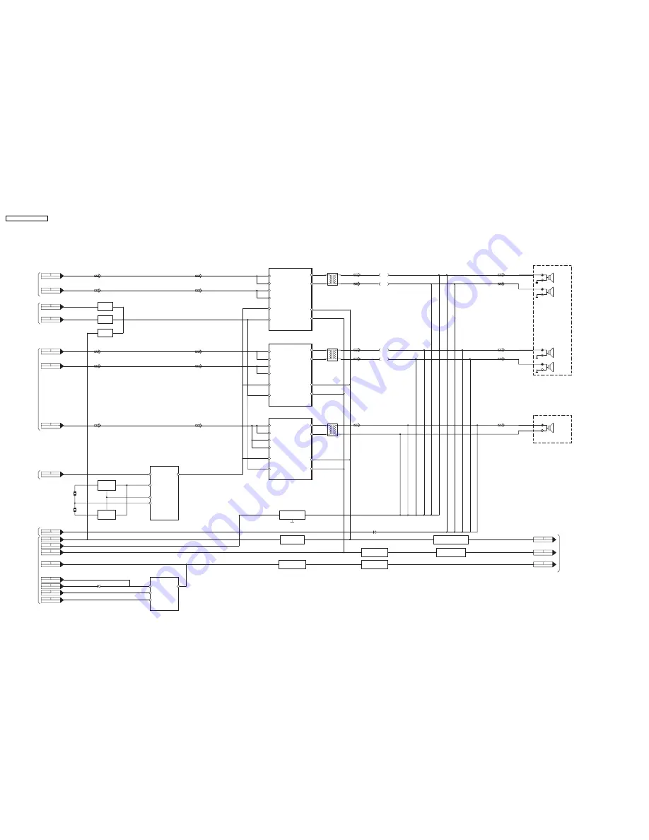
17.5. Power Diagram
SA-
AK750P/PC POWER DIAGRAM
TO TRANSFORMER
TO MAIN
(1/2)
TO MAIN
(2/2)
TO MAIN
(2/2)
TO MAIN
(2/2)
TO MAIN
(1/2)
H5104 CN5950
8
H5104 CN5950
3,4
H5104 CN5950
1,2
CN2809 CN5102
6
CN2809 CN5102
9
CN2809 CN5102
5
CN2809 CN5102
8
CN2809 CN5102
1
CN2809 CN5102
12
CN2808 CN5103
4
CN2808 CN5103
7
CN2808 CN5103
11
CN2808 CN5103
9
CN2808 CN5103
10
CN2808 CN5103
5
CN2808 CN5103
6
CN2808 CN5103
4
CN2809 CN5102
3
CN2808 CN5103
8
RCH.H
RCH.L
LCH.H
LCH.L
RCH
RCH
LCH
LCH
SUBWOOFER
L5501
CN2809 CN5102
11
SPEAKER
RCH.HIGH
SPEAKER
RCH.LOW
JK5101
SPEAKER
JK5102
SUBWOOFER
SPEAKER
LCH.HIGH
SPEAKER
LCH.LOW
X5201
X5202
IC5301
C1AA00000755
2CH DIGITAL AMP
2
3
IN1+
OUT1 10
OUT2 14
VDDA1 20
VSSA1 18
IN1-
21
22
IN2+
IN2-
23
MODE
1
OSC
1
OSC
Q5153
IC5401
C1AA00000755
2CH DIGITAL AMP
2
3
IN1+
IN1-
21
22
IN2+
IN2-
23
MODE
IC5201
C0JBAB000011
LOGIC
IC5101
C0DAZYY00005
REGULATOR IC
1
10
2
3,6
5
4
2
5.6V
VCC
3.3V
CTRL
1
5
MODE
SWITCH
Q5201
FREQUENCY
HOPPING
SWITCH
Q5202
D5130
D5126
FREQUENCY
HOPPING
SWITCH
Q5154
MODE
SWITCH
Q5112,Q5114
CURRENT STABLISER
11V REGULATOR
Q5111
+15V REGULATOR
Q5103,Q5104
FAN ON/OFF SWITCH
Q5113
CURRENT LMIITER
SWITCH
Q5102
CURRENT CONTROL
SWITCH
Q5108,Q5109
SWITCH
VOLTAGE REGULATOR
Q5101,Q5110
CURRENT CONTROL SWITCH
26V REGULATOR
Q5173
SWITCH
L5301
OUT1 10
OUT2 14
VDDA1 20
VSSA1 18
L4301
10
14
1
2
3
21
22
23
OUT1
OUT2
VDDA1
VSSA1
OSC
IN1+
IN1-
IN2+
IN2-
MODE
20
18
IC5501
C1AA00000755
2CH DIGITAL AMP
TO MAIN
(1/2)
OSC
1A
3A
1Y
2A,3Y
5Y
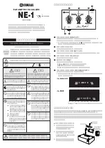
SA-AK750P / SA-AK750PC
64
Summary of Contents for SA-AK750P
Page 8: ...8 SA AK750P SA AK750PC ...
Page 13: ...13 SA AK750P SA AK750PC ...
Page 16: ...With reference to page 13 of the operating instruction manual 16 SA AK750P SA AK750PC ...
Page 18: ...With reference to page 17 of the operating instruction manual 18 SA AK750P SA AK750PC ...
Page 29: ...10 3 Main Parts Location 29 SA AK750P SA AK750PC ...
Page 40: ...10 16 1 Replacement of Pinch Roller and Head Block 40 SA AK750P SA AK750PC ...
Page 47: ...12 4 Checking and Repairing of Power P C B 47 SA AK750P SA AK750PC ...
Page 49: ...Fig 7 49 SA AK750P SA AK750PC ...
Page 53: ...15 2 Power P C B Transformer P C B 15 3 Panel P C B 53 SA AK750P SA AK750PC ...
Page 54: ...15 4 Main P C B 54 SA AK750P SA AK750PC ...
Page 55: ...15 5 XM P C B 15 6 Deck P C B 55 SA AK750P SA AK750PC ...
Page 56: ...15 7 Waveform Chart 56 SA AK750P SA AK750PC ...
Page 58: ...58 SA AK750P SA AK750PC ...
Page 66: ...SA AK750P SA AK750PC 66 ...
Page 68: ...68 SA AK750P SA AK750PC ...
Page 88: ...SA AK750P SA AK750PC 88 ...
Page 93: ...23 Exploded Views 23 1 Cabinet Parts Location SA AK750P SA AK750PC 93 ...
Page 94: ...SA AK750P SA AK750PC 94 ...
Page 95: ...23 2 Deck Mechanism Parts Locations RAA4403 S SA AK750P SA AK750PC 95 ...