


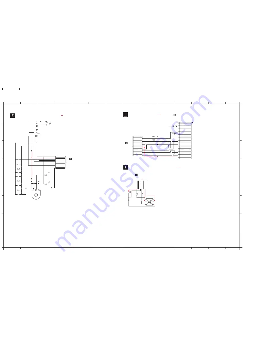
19.5. (E) Sub Panel Circuit, (F) D-Port Circuit & (I) Deck Mechanism Circuit
:+B SIGNAL LINE
:+B SIGNAL LINE
SA-AK750P/PC SUB PANEL/D-PORT/DECK MECHANISM CIRCUIT
SCHEMATIC DIAGRAM - 8
SUB PANEL CIRCUIT
TO
PANEL CIRCUIT
(JW6002)
IN SCHEMATIC
DIAGRAM-7
A
B
C
D
E
F
G
H
1
2
3
4
5
6
7
8
9
10
11
12
13
14
1
2
3
4
5
6
7
8
9
10
11
12
13
14
A
B
D
E
F
H
G
C
DECK MECHANISM CIRCUIT
D6463
D6460
:+B SIGNAL LINE
: IPOD SIGNAL LINE
4
3
1
2
COM B
A
1
3
2
PL
IC971
CNB13030R2AU
PHOTO INTERUPTOR
TO
DECK (CP1902)
ON SCHEMATIC DIAGRAM-11
9
8
7
6
5
4
3
2
1
CS971
MODE HALF
PL_GND
PHOT
O_T
RECINH_F
VREF+ VREF- CR02
R972
820
R973
39K
D971
MA2C16500E
S971
(MODE)
S972 (HALF)
S975
(REC_INH_F)
PL
5
3
2
1
4
10
8
7
6
9
R6303
R6302
S6302
R6304
S6303
K6101
K6104
D6462
R6457
S6301
R6399
R6106
R6491
R6108
S6108
S6106
R6107
R6305
S6304
R6494
R6307
S6309
S6307
S6308
R6308
R6309
R6310
R6306
S6305
S6306
C6491
C6492
R6492
KEY3_2
KEY3
MOT10V
VJOG_A
VOL_LED
STOP/
-DEMO
KEY1
DISPLAY
KEY1 OUT
TAPE
CD
H.BASS_LED
TUNER
H.BASS
PRESENT EQ
REC
SUBW
MUSIC PORT
KEY1 IN
VREF+
GND2
KEY3
OPEN
JW6001
1K
1K
1.2K
0
0
330
10K
2.2K
22K
4.7K
2.7K
1.8K
10K
2.7K
4.7K
6.8K
10K
2.2K
100P
100P
12K
VR6491
EVEKE2F3024B
VOLUME JOG
QR6457
B1GBCFLL0037
LED DRIVE
TO
MAIN CIRCUIT
(CN3400) IN
SCHEMATIC
DIAGRAM - 4
OPTION V.1
(TO DOCK)
C3001
0.1u
R3001
330K
R3002
220K
7
9
11
10
12
8
2
3
1
5
6
4
13
6
7
5
9
13
15
14
11
10
12
21
22
18
16
17
20
19
8
1
3
4
2
24
23
CN2401
DOCK_R IN
DOCK_DET2
BATT2
IPOD_DET
VBUS
DOCK5V
DOCK_DET1
DO_UART_IN
DOCK_UOUT
DOCK5V
DOCK5V
DOCK5VGND
(MIC_VCC) (RF_MUTE)
DOCK_DET2
UART_IN
AD_CTRL
IPOD_DET
(A/D CONT) (RF_SEL)
V_GND
GND
D-
NC
A_GND
DOCK_LOUT
IPOD_ACC
BATT_GND
DOCK_LIN
RESERVED
DOCK_R OUT
D+
VIDEO
DO_UART_OUT
DOCK_R
DOCK_DET1
AGND
DOCK_L
DOCK5VGND
CN806A
D-PORT CIRCUIT
D6457
R6460
560
D6457,D6462
B3ACA0000302
WA3002
0
WA3004
0
WA3001
0
WA3003
0
SA-AK750P / SA-AK750PC
76
Summary of Contents for SA-AK750P
Page 8: ...8 SA AK750P SA AK750PC ...
Page 13: ...13 SA AK750P SA AK750PC ...
Page 16: ...With reference to page 13 of the operating instruction manual 16 SA AK750P SA AK750PC ...
Page 18: ...With reference to page 17 of the operating instruction manual 18 SA AK750P SA AK750PC ...
Page 29: ...10 3 Main Parts Location 29 SA AK750P SA AK750PC ...
Page 40: ...10 16 1 Replacement of Pinch Roller and Head Block 40 SA AK750P SA AK750PC ...
Page 47: ...12 4 Checking and Repairing of Power P C B 47 SA AK750P SA AK750PC ...
Page 49: ...Fig 7 49 SA AK750P SA AK750PC ...
Page 53: ...15 2 Power P C B Transformer P C B 15 3 Panel P C B 53 SA AK750P SA AK750PC ...
Page 54: ...15 4 Main P C B 54 SA AK750P SA AK750PC ...
Page 55: ...15 5 XM P C B 15 6 Deck P C B 55 SA AK750P SA AK750PC ...
Page 56: ...15 7 Waveform Chart 56 SA AK750P SA AK750PC ...
Page 58: ...58 SA AK750P SA AK750PC ...
Page 66: ...SA AK750P SA AK750PC 66 ...
Page 68: ...68 SA AK750P SA AK750PC ...
Page 88: ...SA AK750P SA AK750PC 88 ...
Page 93: ...23 Exploded Views 23 1 Cabinet Parts Location SA AK750P SA AK750PC 93 ...
Page 94: ...SA AK750P SA AK750PC 94 ...
Page 95: ...23 2 Deck Mechanism Parts Locations RAA4403 S SA AK750P SA AK750PC 95 ...


