21
6.5.
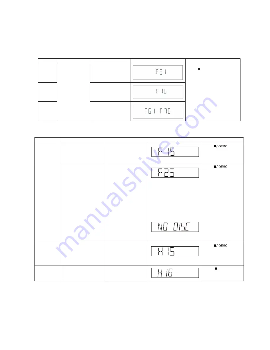
Self-Diagnostic Error Code Table
Self-Diagnostic Function (Refer Section 6.4. Self-Diagnostic Mode) provides information on any problems occurring for the unit and
its respective components by displaying the error codes. These error code such as U**, H** and F** are stored in memory and held
unless it is cleared.
The error code is automatically display after entering into self-diagnostic mode.
6.5.1.
Power Supply Error Code Table
6.5.2.
Mechanism Error Code Table (CD Mechanism Unit (DLS6C))
Error Code Diagnosis Contents Description of error
Automatic FL Display
Remarks
F61
Power Amp IC output
abnormal
Upon
power
on,
PCNT=HIGH,
DCDET2=L
after checking LSI.
Press [
] on main unit for
next error.
F76
DCDET1 = L (NG)
F61-76
Both
DCDET1
and
DCDET2
L (NG)
-DEMO
Error Code
Diagnosis Contents
Description of error
Automatic FL Display
Remarks
F15
CD REST SW Abnormal
Press [
] on main
unit for next error.
F26
Communication between
CD servo LSI and micro-p
abnormal.
Press [
] on main
unit for next error.
H15
CD Open SW Abnormal
During normal operation
CD OPEN SW On fail to be
detected with 3 sec.
Press [
] on main
unit for next error.
CD traverse position initial
setting operation fail safe
time is over (10 sec) waiting
for REST SW to turn on.
At the time of switching to
CD function,SENSE = H
shall be detected using
DTMS system setting
command. If the error is
memorized when SENSE
= L is not detected within
fail safe timer time (20ms),
[F26] shall be displayed
simultaneously.This
display shall be retained if
the power is ON and at
CD function. If this error
occurs, CD operation
afterwards shall not be
executed as in the case of
[NO DISC].
H16
CD closing SW abnormal
During Closing operation,if
"POS_SW_CEN" is not
detected within 3 secs.
Press [ /-DEMO]on main
unit for next error.
Summary of Contents for SA-AKX10PH
Page 14: ...14 5 2 Remote Control Key Button Operation ...
Page 15: ...15 5 3 Media Information ...
Page 25: ...25 7 2 3 D Amp P C B Fig 3 D Amp P C B D Amp IC IC5900 ...
Page 31: ...31 9 2 Main Components and P C B Locations ...
Page 57: ...57 Step 5 Detach 16P FPC at the connector CN7001 on CD Servo P C B ...
Page 78: ...78 ...
Page 80: ...80 ...
Page 104: ...104 ...


