21
8 Disassembly and Assembly Instructions
• Illustration is based on SA-AKX18PH-K.
• This section describes the disassembly and/or assembly procedures for all major printed circuit boards & main compo-
nents for the unit. (You may refer to the section of “Main components and P.C.B Locations” as described in this service
manual)
• Before carrying out the disassembly process, please ensure all the safety precautions & procedures are followed.
• During the disassembly and/or assembly process, please handle with care as there may be chassis components with
sharp edges.
• Avoid touching heatsinks due to its high temperature after prolong use.
• Be sure to use proper service tools, equipments or jigs during repair.
• Select items from the following indexes when disassembly or replacement are required.
• Disassembly of Top Cabinet
• Disassembly of Front Panel Unit
• Disassembly of Panel P.C.B. and LCD P.C.B.
• Disassembly of USB P.C.B.
• Disassembly of Rear Panel
• Disassembly of Main P.C.B.
• Disassembly of SMPS Module and Voltage Selector P.C.B.
• Disassembly of CD Mechanism Unit
• Disassembly of CD Interface P.C.B.
8.1.
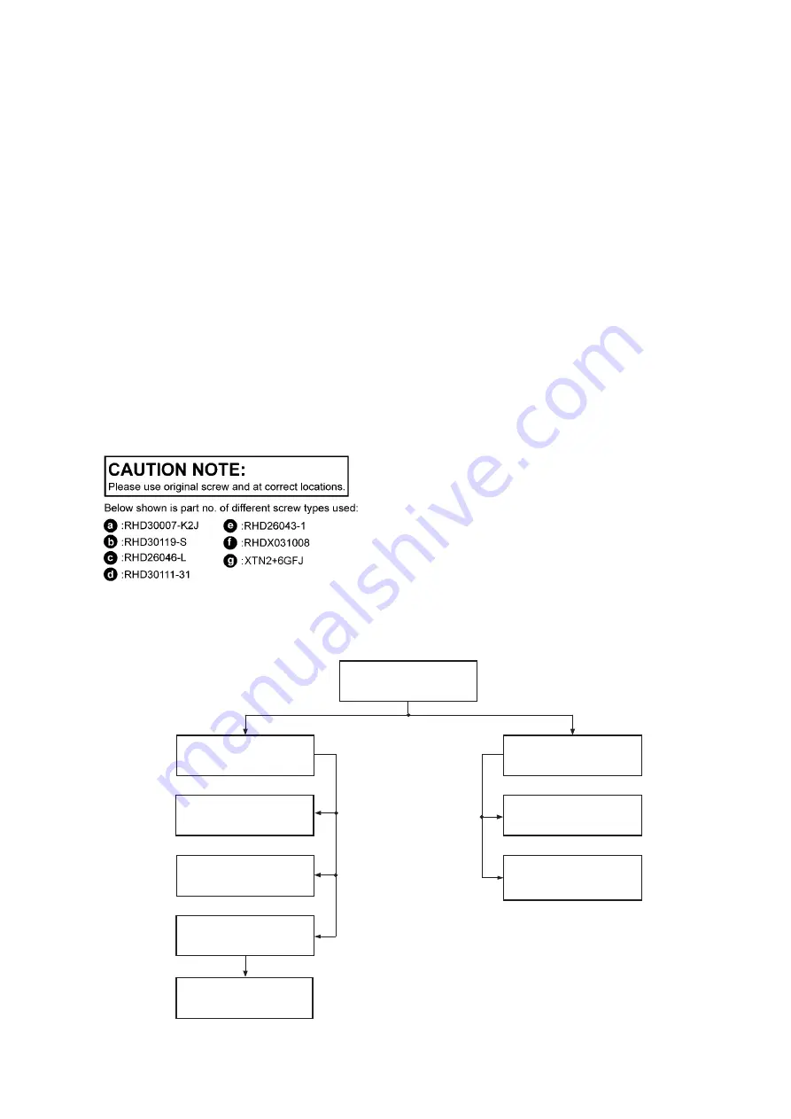
Type of Screws
8.2.
Disassembly Flow Chart
8.9. Main P.C.B.
8.11. CD Mechanism
Unit
8.8. Rear Panel
8.1
2
. CD Interface
P.C.B.
8.5. Front Panel Unit
8.4. Top Cabinet
8.6. Panel P.C.B. and
LCD P.C.B.
8.7. USB P.C.B.
8.10. SMPS Module
and Voltage
Selector P.C.B.
Summary of Contents for SA-AKX18PH
Page 22: ...22 8 3 Main Components and P C B Locations ...
Page 30: ...30 ...
Page 36: ...36 ...
Page 38: ...38 ...
Page 52: ...52 ...
Page 60: ...60 ...
Page 68: ...68 MMH1401 ...


