118
(VOLTAGE SELECTOR P.C.B.)
^
(SMPS P.C.B.)
(MAIN P.C.B.)
(CD SERVO P.C.B.)
(CD INTERFACE P.C.B.)
*ZJ5000
*ZJ2001
ZJ2000
*TL8
*TL7
*TL6
*TL5
T5751
T5701
S7201
S5701
^
P5701
JK5601
JK2000
JK52
JK51
*HEATSINK UNIT C
*HEATSINK UNIT B
FP9003
FP8101
FP8251
FP8201
F1
*HEATSINK
CN7002
CN7001
CN5802
CN2700
CN2009
CN2007
CN2005
CN2003
CN2002
(BRS11C)
310
310
310
301
45
43
42
41
29
29
29
29
29
27
26
26
23
23
22
22
21
19
19
17
17
17
16
16
15
15
15
15
15
15
15
15
15
^
^
14
14
14
14
14
14
14
14
14
14
9
^
8
^
6
5
4
2
1
a
c
e
e
f
f
g
h
h
i
i
j
j
k
k
l
l
m
m
1
2
3
4
5
6
7
8
9
A
B
C
D
E
F
G
H
10
11
12
13
" ^ " PART IS FOR PH ONLY.
NOTE: " * " PART IS NOT SUPPLIED / REF IS FOR INDICATION ONLY.
SA-AKX54PH/PN-K
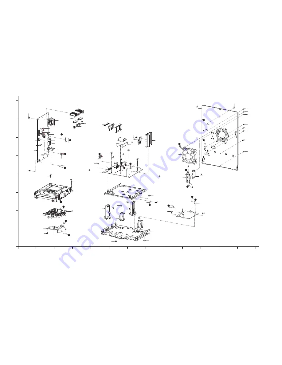
CABINET DRAWINGS
Summary of Contents for SA-AKX54PH
Page 13: ...13 5 General Introduction 5 1 Media Information ...
Page 14: ...14 6 Location of Controls and Components 6 1 Remote Control Key Button Operation ...
Page 15: ...15 6 2 Main Unit Key Button Operation ...
Page 16: ...16 7 Installation Instructions 7 1 Speaker and A C Connection ...
Page 18: ...18 8 2 Doctor Mode Table 8 2 1 Doctor Mode Table 1 ...
Page 25: ...25 9 1 2 Main P C B Front side Fig 2 Main P C B ...
Page 28: ...28 9 3 D Amp IC Operation Control ...
Page 33: ...33 11 2 Main Components and P C B Locations ...
Page 66: ...66 ...
Page 76: ...76 ...
Page 78: ...78 ...
Page 120: ...120 ...


