background image

38

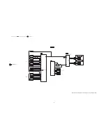
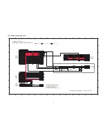
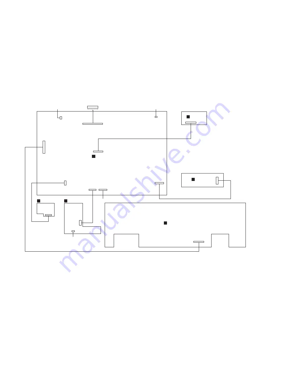
11 Wiring Connection Diagram

SA-AKX600LM, SA-AKX800LM WIRING CONNECTION DIAGRAM

TO OPTICAL PICKUP UNIT 

(CD MECHANISM UNIT)

SMPS MODULE

TO FAN UNIT

TO FAN UNIT

TO CD LOADING P.C.B.

(CD MECHANISM UNIT)

P5102

P5002

CN6100

CN2511

CN2507

CN2506

CN2103

CN2102

CN2101

10P

24P

15P

9P

4P

22P

13P

2P

2P

CN6100

22P

CN6402

9P

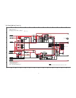
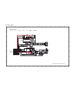
CN6300

4P

CN51

15P

CN7001

CN7002

5P

10P

MUSIC PORT P.C.B.

E

USB P.C.B.

D

CD INTERFACE P.C.B.

F

MAIN P.C.B.

A

PANEL P.C.B.

C

TUNER P.C.B.

B

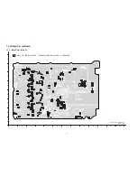
Summary of Contents for SA-AKX600LM

Page 1: ...autions for Traverse Unit 2 5 Grounding for electrostatic breakdown prevention 3 Service Navigation 3 1 Service Information 4 Specifications 5 Location of Controls and Components 5 1 Remote Control Key Button Operation 5 2 Main Unit Key Button Operation 6 Service Mode 6 1 Cold Start 6 2 Sales Demonstration Lock Function 6 3 Doctor Mode Table 6 4 Self Diagnostic Mode 6 5 Self Diagnostic Error Code ...

Page 2: ...t 12 4 Main SOC IO Expander Circuit 1 2 12 5 Main SOC IO Expander Circuit 2 2 12 6 Main Damp Circuit 1 2 12 7 Main Damp Circuit 2 2 12 8 Main Connector Circuit 12 9 Main DSP Circuit 12 10 Main VREG Fan Circuit 1 2 12 11 Main VREG Fan Circuit 2 2 12 12 Tuner Circuit 12 13 Panel Circuit 12 14 USB CD Interface and Music Port Circuit 13 Printed Circuit Board 13 1 Main P C B Side A 13 2 Main P C B Side...
Page 3: ...ock hazards 1 1 1 Leakage Current Cold Check 1 Unplug the AC cord and connect a jumper between the two prongs on the plug 2 Measure the resistance value with an ohmmeter between the jumpered AC plug and each exposed metallic cabinet part on the equipment such as screwheads connectors control shafts etc When the exposed metallic part has a return path to the chassis the reading should be between 1M...

Page 4: ...rotection circuitry may have operated if either of the following conditions are noticed No sound is heard when the power is turned on Sound stops during a performance The function of this circuitry is to prevent circuitry damage if for example the positive and negative speaker connection wires are shorted or if speaker systems with an impedance less than the indicated rated impedance of the amplif...

Page 5: ...5 1 4 Power Supply using SMPS Module This model uses Switching Mode Power Supply SMPS Module to provide the power supply to the unit Here is the supplied part no for the Module 1 N0AB2GP00003 Figure 1 3 ...

Page 6: ...ds Do not modify the original design without permission of manufacturer Model SC AKX600LM Safety K2CB2CB00022 RKM0765 KL RKM0765Z K RD DDL112 PX RQT0A34 1M N0AB2GP00003 CD UNIT RGR0473B G Part No SWITCHING POWER SUPPLIES AC DC CONVERTER TOP CABINET BEND TOP CABINET UNBENT AC CORD O I BOOK SP Part Name REAR PANEL Model SC AKX800LM Safety K2CB2CB00022 RKM0765 KL RKM0765Z K RD DDL112 PX RQT0A34 1M N0...

Page 7: ...nt to damage ES devices 6 Do not remove a replacement ES device from its protective package until immediately before you are ready to install it Most replacement ES devices are packaged with leads electrically shorted together by conductive foam aluminum foil or compara ble conductive material 7 Immediately before removing the protective material from the leads of a replacement ES device touch the...

Page 8: ...e Parts Route The following 3 types of lead free solder are available through the service parts route RFKZ03D01K 0 3mm 100g Reel RFKZ06D01K 0 6mm 100g Reel RFKZ10D01K 1 0mm 100g Reel Note Ingredient tin Sn 96 5 silver Ag 3 0 Copper Cu 0 5 Cobalt Co Germanium Ge 0 1 to 0 3 2 4 Handling Precautions for Traverse Unit The laser diode in the optical pickup unit may break down due to static electricity ...

Page 9: ...royed by the static electricity of the working environ ment Repair in the working environment that is grounded 2 5 1 Worktable grounding Put a conductive material sheet or iron sheet on the area where the optical pickup is placed and ground the sheet 2 5 2 Human body grounding Use the anti static wrist strap to discharge the static electricity form your body Figure 2 2 Figure 2 2 ...

Page 10: ... Note Please do not rename the file as the updating process will look for above naming If different name version up process will not work To create USB update copy the desired FRM file depends on model into USB device Please make sure there is no other files inside the USB device Step 2 Software Update Caution Ź During the update process do not disconnect the AC power supply cord Ź Do not press an...

Page 11: ...e p 3 p M 3 P M t a m r o f e l i f g n i d r o c e R Bluetooth section General Power supply AC 127 V 60 Hz Power consumption 173 W Dimensions W x H x D 348 mm x 192 mm x 303 mm Weight 3 6 kg Operating temperature range 0 C to 40 C Operating humidity range 35 to 80 RH no condensation Power Consumption in standby mode Power Consumption in standby mode With BLUETOOTH STANDBY set to ON 9 2 Wh day app...

Page 12: ...12 5 Location of Controls and Components 5 1 Remote Control Key Button Operation ...

Page 13: ...13 5 2 Main Unit Key Button Operation ...

Page 14: ...n the unit 2 Select to any mode function 3 Press and hold OPEN CLOSE and CD RADIO AUX keys for 5 sec or more The display will show upon entering into this mode for 2 sec Note OPEN CLOSE button is invalid and the main unit displays LOCKED while the lock function mode is entered Cancellation of Sales Demonstration Lock Mode To cancel sales demonstration lock mode 1 Turn on the unit 2 Select to CD mo...

Page 15: ...w by 4 and 7 on remote control In CD mode 1 Enter into Doctor Mode 2 To exit press DELETE button on remote control or press POWER I button on Main Unit Displaying of 1 Year Develop 2 Model Type 3 ROM Type 4 Firmware Version Display 2 For AKX800 Cold Start To active cold start upon next AC power up when reset start is execute the next time In Doctor Mode 1 Press 4 button on the remote control Versi...

Page 16: ...reach 99999999 will change to 00000000 Cancellation Display Traverse Test To determine traverse unit operation for inner outer access track The counter will increment by one When reach 99999999 will change to 00000000 The counter will increment by one When reach 99999999 will change to 00000000 Cancellation Display Reliability Test Combination In this mode ensure the CD is in the main unit To dete...

Page 17: ...rol Step 2 Press hold g button follow by y i on main unit for 2 seconds Error Code Information System will perform a check on any unusual error code from the memory Example Step 1 In self diagnostic mode Press g on main unit To exit press 8 on main unit or remote control Delete error code To clear the stored in memory EEPROM IC Step 1 In self diagnostic mode Press 0 on remote control FL Display Ke...

Page 18: ...r during cold start Error Code F26 Diagnosis Contents Communication between CD servo LSI and micro p abnormal During switch to CD function if SENSE L within fail safe time of 20ms Press g on main unit for next error Press g on main unit for next error Press g on main unit for next error FL Display Key Operation Front Key Item Description Mode Name Error Code F70 Diagnosis Contents Bluetooth Commun...

Page 19: ...19 7 Troubleshooting Guide Contents for this section is not available at time of issue ...

Page 20: ... to its high temperature after prolong use See caution as described below During disassembly and assembly please ensure proper service tools equipments or jigs is being used During replacement of component parts please refer to the section of Replacement Parts List as described in the ser vice manual Select items from the following indexes when disassembly or replacement are required Disassembly o...

Page 21: ...sassembly Flow Chart 8 3 Main Components and P C B Locations Main P C B SMPS Module Tuner P C B Rear Panel CD Mechanism Unit CD Interface P C B Front Panel Unit Top Cabinet Panel P C B USB P C B Music Port P C B ...

Page 22: ...release both sides of Top Cabinet Step 5 Slightly lift up to remove Top Cabinet 8 5 Disassembly of Front Panel Unit Refer to Disassembly of Top Cabinet Step 1 Detach 9P Cable at connector CN2511 on Main P C B Step 2 Detach 22P FFC at connector CN2506 on Main P C B Step 3 Detach 4P Cable at connector CN2507 on Main P C B ...

Page 23: ...tom of unit Step 5 Detach to remove Front Panel Unit 8 6 Disassembly of Panel P C B Refer to Disassembly of Top Cabinet Refer to Disassembly of Front Panel Unit Step 1 Remove Volume Knob Step 2 Remove 2 screws Step 3 Release catches Step 4 Lift up to remove Panel P C B ...

Page 24: ...o remove USB P C B 8 8 Disassembly of Music Port P C B Refer to Disassembly of Top Cabinet Refer to Disassembly of Front Panel Unit Step 1 Remove screw Step 2 Lift up to remove Music Port P C B 8 9 Disassembly of Rear Panel Refer to Disassembly of Top Cabinet Step 1 Remove 10 screws Step 2 Lift up Wire Clamper Step 3 Detach 2P Wire at connector CN2102 on Main P C B ...

Page 25: ... of Rear Panel Step 1 Detach 13P Cable at connector CON2 on SMPS Mod ule Step 2 Detach 2P Wire at connector CN2101 on Main P C B Step 3 Detach 15P FFC at connector CN6100 on Main P C B Step 4 Remove 3 screws Step 5 Lift up to detach Main P C B Step 6 Detach 10 FFC at connector P5102 on Main P C B Step 7 Detach 24P FFC at connector P5002 on Main P C B Step 8 Remove Main P C B ...

Page 26: ...3P Cable at connector CON2 on SMPS Mod ule Step 2 Remove 3 screws Step 3 Release P C B Spacer Step 4 Remove SMPS Module 8 12 Disassembly of Tuner P C B Refer to Disassembly of Top Cabinet Refer to Disassembly of Rear Panel Step 1 Remove screw Step 2 Detach 15P FFC at connector CN51 on Tuner P C B Step 3 Remove Tuner P C B ...

Page 27: ...net Refer to Disassembly of Front Panel Unit Refer to Disassembly of Rear Panel Refer to Disassembly of Main P C B Step 1 Remove screw Step 2 Remove screw Step 3 Release catches Step 4 Lift up to remove Inner Chassis Unit Step 5 Remove 2 screws Step 6 Remove CD Mechanism Unit ...

Page 28: ...isassembly of Front Panel Unit Refer to Disassembly of Rear Panel Refer to Disassembly of Main P C B Refer to Disassembly of CD Mechanism Unit Step 1 Remove 2 screws Step 2 Desolder pins of the motor M7301 Step 3 Desolder pins of the motor M7302 Step 4 Remove CD Interface P C B XTN2 6GFJ g ...

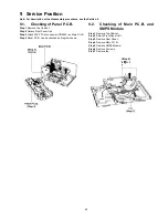
Page 29: ... 2 Detach Front Panel Unit Step 3 Attach 22P FFC at connector CN2506 on Main P C B Step 4 Panel P C B can be checked as diagram shown 9 2 Checking of Main P C B and SMPS Module Step 1 Remove Top Cabinet Step 2 Detach Front Panel Unit Step 3 Remove Rear Panel Step 4 Remove Main P C B Step 5 Remove SMPS Module Step 6 Remove 2 screws Step 7 Remove fan ...

Page 30: ...ch 10 FFC at connector P5102 on Main P C B Step 11 Attach 24P FFC at connector P5002 on Main P C B Step 12 Attach 13P Cable at connector CON2 on SMPS Mod ule Step 13 Attach 2P Wire at connector CN2101 on Main P C B Step 14 Attach 2P Wire at connector CN2102 on Main P C B Step 15 Main P C B and SMPS Module can be checked as dia gram shown ...

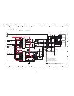
Page 31: ...5102 SPINDLE MOTOR M7302 TRAVERSE MOTOR M7301 CD INTERFACE P C B 3 3V Q5001 LASER DRIVE D L N I V 3 2 5CH MOTOR DRIVER IC5001 7 1 D L O V 8 1 D L O V 1 1 L S O V 2 1 L S O V VOFC 14 3 1 C F O V 6 1 K T O V VOTK F F T T CD LD MD LPD 15 VOTR 10 VOTR 9 K T N I V 6 2 7 REV 6 FWD 23 P5002 24 P5002 21 P5002 22 P5002 6 P5002 5 P5002 OPEN SW 3 CN7001 CLOSE SW 1 CN7001 1 VINFC 16 P5002 15 P5002 20 P5002 19...

Page 32: ...04 D6105 D6106 2 21 CN6100 CN2506 1 22 CN6100 CN2506 RED LED GREEN LED RED LED GREEN LED 19 4 CN6100 CN2506 BLUE LED BLUE LED 1 CN2502 SUBW LED SUPPLY 3 CN2502 BLUE LED 4 CN2502 GREEN LED 2 CN2502 RED LED 5 6V 5 6V LED LIGHTING CIRCUIT Q6000 SWITCH QR6000 SWITCH QR2505 LED DRIVE QR2502 LED DRIVE QR2503 LED DRIVE P2 3 P0 1 P3 4 SPEAKER IC8006 FOR AKX800 D6201 17 CN2506 15 CN2506 16 CN2506 FL SDO FL...

Page 33: ...IC8006 FAN OUT DC DET AMP FAN CONTROL IC2102 Q2100 Q2103 Q2104 Q2106 Q2108 Q2110 Q2111 Q2112 15V FAN UNIT REAR POSITIVE NEGATIVE CN2102 CN2102 2 1 FAN UNIT INTERNAL POSITIVE NEGATIVE CN2101 CN2101 2 1 FAN CONTROL CIRCUIT GPIO16 108 USB B OVC FROM TO AUDIO 0 4 6 N I D A ILLUMINATION PCONT GPIO12 95 PDET 36V GPIO10 13 SYNC TUN INT TUN SDO LRCKO1 83 BCKO1 82 DATAO1 81 TUN WCK GPIO18 116 DATAI1 112 LR...

Page 34: ...1 S F D LIN 15 RIN 16 7 1 K L C D SDIO RST JK52 L52 4 6 3 1 2 4 AMI 2 1 AM ANT FROM TO SYSTEM CONTROL 3 COM Y 13 COM X TUN BCK I2C SCL TUN RST TUN SDO MPORT DET PWM1B PWM1A PWM2B PWM2A PWM3B PWM3A PWM4B PWM4A FL HI FL HI FR HI FR HI F LO F LO SW SW 27 28 29 30 31 32 33 34 OUTL 6 OUTR 7 SDOUT2 17 14 DIN 13 BCK 15 LRCK 1 DAMP RST MUSIC PORT P C B R L AUX IN 2 JK6301 3 2 1 6 7 5 4 1 1 CN6300 CN2507 1...

Page 35: ... INPUT A INPUT B OUT A BST A OUT B BST B OUT A OUT D BST D OUT C BST C OUT D DC DETECT CIRCUIT OTW FAULT INPUT B RST INPUT A OTW FAULT RST 36V D3000 D3001 17 16 6 4 5 39 40 44 35 43 28 27 23 32 24 OUT D BST D OUT C BST C OUT D 28 27 23 32 24 17 16 4 39 40 44 35 43 28 27 23 32 24 17 16 4 5 6 39 40 44 35 43 17 16 14 15 4 5 6 39 40 44 35 43 28 27 23 32 24 DC DET AMP F LO F LO FL HI FL HI FR HI FR HI ...

Page 36: ...S BP 5 6 7 CN2103 40V 9 CN2103 SYS5V 8 CN2103 SYNC 10 CN2103 SMPS ID SMPS MODULE AC INLET SMPS MODULE H P 0 1 3 EN 1 BOOT 7 VSENSE 2 VIN 5 6V DC DC CONVERTER IC2101 H P 0 1 3 EN 1 BOOT 7 VSENSE 2 VIN 15V DC DC CONVERTER IC2103 D2111 Q2113 12V VOLTAGE REGULATOR Q2119 DC DETECT Q2117 QR2102 5V STANDBY CONTROL CIRCUIT PW STDBY 3R3V 3 3V PW 1R5V 1 5V PW MUX 12V 12V 15V DC DC 15V PW 36V 36V PW CD 5R6V ...

Page 37: ...03 USB HIGH SIDE SWITCH 5 VIN VOUT 1 USB B SW5R1V 5V 4 EN 3 OC USB5V 5V 6 6 CN6402 CN2511 USB A SW5R1V USB A SW5R1V USB5V 5V 7 7 CN6402 CN2511 USB B SW5R1V USB B SW5R1V PW CD 5R6V 5 PW CD 3R3V PW MUX 12V 2 15V 3 DC DET PWR 1 4 PW STDBY 3R3V D2100 5 6V 5 6V 16 7 CN6100 CN2506 PW CD3R3V 17 6 CN6100 CN2506 PW CD5R6V 3 3V 3 3V 3 3V 3 3V PW CD3R3V 7 9 CN51 CN6100 PW CD 3R3V 3 3V 3 3V PW CD 3R3V 4 12 CN...

Page 38: ...T SMPS MODULE TO FAN UNIT TO FAN UNIT TO CD LOADING P C B CD MECHANISM UNIT P5102 P5002 CN6100 CN2511 CN2507 CN2506 CN2103 CN2102 CN2101 10P 24P 15P 9P 4P 22P 13P 2P 2P CN6100 22P CN6402 9P CN6300 4P CN51 15P CN7001 CN7002 5P 10P MUSIC PORT P C B E USB P C B D CD INTERFACE P C B F MAIN P C B A PANEL P C B C TUNER P C B B ...

Page 39: ...citor Unit of capacitance is μF unless otherwise noted F Farads pF pico Farad Coil Unit of inductance is H unless otherwise noted REF IS FOR INDICATION ONLY Voltage and signal line S6200 Power switch S6201 Open Close switch S6202 Stop Tune switch S6211 D Bass switch S6212 Album Track Illumination switch S6213 Forward switch S6214 CD Radio AUX switch S6215 Play Pause switch S6216 DJ Jukebox Sampler...

Page 40: ... R5012 0 C5015 10P C5016 10P C5013 100P C5014 10P J0JYC0000322 LB5004 0 R5039 68K R5006 68K R5005 2200P C5008 2200P C5007 1 2K R5009 R5010 1K 10V100 C5011 0 1 SPM SPM LB5010 J0JBC0000010 T T J0JBC0000010 LB5011 C5019 C5012 1000P LDM J0JYC0000322 LB5003 TRV TRV LDM C5010 0 01 10 C5009 LB5007 J0JBC0000010 F LB5006 J0JBC0000010 F J0JBC0000010 LB5009 J0JBC0000010 LB5008 R5008 100 2 1 27 5 4 24 25 22 8...

Page 41: ...5 106 103 104 108 110 109 107 91 89 87 85 34 83 36 81 39 38 78 0 7 9 6 2 6 3 6 1 6 5 5 4 5 51 50 53 52 6 5 8 5 7 5 0 4 2 4 3 4 1 4 46 45 8 4 7 4 9 4 44 60 59 8 6 6 6 7 6 5 6 4 6 72 75 74 77 76 73 71 79 RD DAK153 PX AKX600LM RD DAK152 PX AKX800LM 2GB NAND FLASH MEMORY IC2001 R2006 47K R2003 47K R2001 47K LB9001 0 LB9003 0 D9001 B0ECKM000008 EMMC_NRST 47K R2005 USB_B_OVC 0 R1123 PW_CD_ 5R6V USB_A_PC...

Page 42: ...0010 1 2K R1107 R1108 1 2K CD GND VOUT VIN IC1001 C1AB00004188 SOC DVSS DATAO2 FLASH_CS DVDD_M2 GPIO10 BCKO1 SVDD SVSS DATAO1 DVDDIO LRCKO1 DATAO2 BCKO1 DATAO1 LRCKO1 SD_CLK SD_CMD SD_DAT3 SD_CON DVDDIO SD_DAT1 SD_DAT0 FLASH_CLK FLASH_DAT3 FLASH_DATA 96 AVDDC 95 GPIO12 94 GPIO11 128 XOUT_PLL 127 XIN_PLL 126 TMODE 125 XOUT_32K SVSS REGION 1 DVSS SVDD DVDD_M1 VDDQ SD_DAT2 VSSQ GPIO0 FLASH_DAT2 MODEL...

Page 43: ...26 3 9K R1227 0 SWITCH 100 R1219 100 R1220 100 R1206 100 R1223 100 R1208 100 R1209 100 R1210 100P C1202 R1214 100 100 R1215 100 R1217 100 R1216 100P C1203 100P C1201 4 7 C1204 100 R1207 100 R1225 SP_CLR SP_STB 26 25 27 28 17 18 20 22 24 23 21 19 8 7 5 6 16 15 10 9 13 14 11 12 3 1 2 30 32 31 4 29 C0JBAZ002990 IO EXPANDER IC8006 SP_SDA SP_SCL SYS5V_GND P11 P10 VDD P14 CLR P2 P7 P9 P8 P6 P5 STB P1 P4...

Page 44: ...0 1 C3005 0 1 C3004 R3102 22K C3007 0 1 0 1 C3102 10 R3100 C3103 0 1 C3105 0 1 C3104 0 1 100 R3009 0 033 C3107 C3108 0 033 1 C3112 C3111 0 1 1 C3118 C3117 0 1 R3017 0 R3016 0 C3027 0 033 C3026 0 033 R3003 100 R3001 10 C3002 0 1 C3001 10 R3559 0 R3560 0 C3100 10 R3101 10 100 R3103 R3011 10 C3101 0 1 R3005 0 R3004 0 FR LO FR LO GND FL LO FL LO 2 1 4 43 11 9 10 34 36 35 12 33 6 7 5 39 38 41 40 8 37 2...

Page 45: ... C3303 C3307 0 1 C3306 C3326 C3327 0 033 0 033 C3309 C3308 0 033 0 033 C3310 0 1 R3541 100 C3205 0 1 R3303 R3305 C3302 0 1 C3301 10 R3301 100 10 R3309 100 R3302 C3305 C3304 0 1 0 1 22K 0 1 0 1 R3304 0 0 C3211 0 1 C3212 1 C3203 0 1 FR LO FR LO FR LO FR LO GND FL LO FR HI SW _3 SW _3 FL HI FL LO FL LO FL LO FL HI FR HI FR HI FR HI FR LO FR LO FL HI FL HI FL LO FL LO OTW FAULT 2 1 4 43 11 9 10 34 36 ...

Page 46: ...521 LB2522 J0JBC0000010 J0JBC0000010 LB2523 6 5 8 9 11 12 10 18 15 17 16 20 19 13 14 7 2 1 1 4 3 22 22 21 CN2506 BLUE_LED GREEN_LED USBLED_B USBLED_A USB_B_SW5R1V D A D B D B D A DGND USB_A_SW5R1V SUBW_LED_SUPPLY RED_LED I2C_SDA TUN_RST TUN_INT TUN_WCK AGND MPORT_L MPORT_R TUN_SD0 ANA_SEL2 ANA_SEL1 I2C_SCL PW_MUX_ 12V PW_CD_3R3V G_TUN_BCK CD3R3_GND MPORT_DET MPORT_R AGND MPORT_L DGND DGND ADC_GND ...

Page 47: ... 1 3 32 34 36 35 33 1 4 0 4 2 4 43 8 3 9 3 7 3 8 6 1 7 1 5 1 13 14 9 6 7 27 25 22 23 20 19 21 24 26 18 30 31 28 29 THERMAL PAD 11 12 10 IC4001 VUEALLPT090 DSP SDIN1 SDIN2 LRCK PWM2B PWM2A PWM1A PWM1B DVDD_PWM1 REG15 DVDDCORE BCKO LRCK DVDD2 CLKO VALID DVSS2 ERRIN SDOUT2 SDOUT1 LDOPOFF BCK DVDD1 12 DVSSCORE DVSS_PWM1 25 XINSEL ADDR TST BSSEL SCL SDA SMUTE RST_N SDIN3 1 DVSS1 DIVSEL CLK110M AVDD AVS...

Page 48: ...DZ2J130M0L D2104 LB2103 J0JHC0000046 R2156 820 C2179 0 1 Q2113 B1AAJC000019 12V VOLTAGE REGULATOR 0 01 C2134 C2135 25V220 C2115 25V33 LB2102 J0JHC0000046 C2155 25V100 100K R2165 82K R2164 10K R2166 LB2101 J0JHC0000046 0 R2244 B1GBCFJJ0041 DC DETECT Q2119 R2245 1K DZ2J130M0L D2111 C2107 10V220 0 R2191 R2199 0 B0JCPG000032 D2106 G1C470MA0445 L2101 B0JCPG000032 D2107 L2102 G1C330MA0291 10 C2142 0 1 C...

Page 49: ...20 C2124 C2126 0 1 B1ABCF000231 FAN CONTROL Q2108 R2143 27 B1ABCF000231 Q2106 27 R2155 B1ABCF000231 FAN CONTROL Q2112 1 2 CN2102 1 2 CN2101 C2133 0 01 R2152 0 1 D2103 DA2J10100L 82K R2150 220 R2151 C2131 1 R2153 470K R2148 6 8K R2149 270K 100 R2154 0 R2147 C2129 1 6 3V100 C2130 B1ABCF000231 FAN CONTROL Q2110 6 3V220 C2132 Q2111 B1ABCF000231 FAN CONTROL DAMPGND B1GBCFJJ0040 PCONT QR2102 4 7K R2200 ...

Page 50: ... C6121 J0JBC0000134 LB6100 0 1 C6101 C6107 1 7 5 1 6 2 4 3 10 12 14 15 16 13 11 8 9 IC6100 C0JBAR000367 SELECTOR R79 0 0 R60 R59 2 2K R6106 4 7K 4 7K R6107 L51 G1CR18JA0020 C51 1000P C6108 1 C6123 1 C6110 10 R6148 47K 47K R6149 C6122 1 10K R6150 10K R6151 33P C66 J0JYC0000118 LB52 R73 0 R74 0 R57 1K 0 1 C62 6P C63 C65 3P 560 R52 R50 0 R80 0 R76 0 C6217 1 4 12 1 2 14 T1 16 17 18 19 15 20 3 13 THERM...

Page 51: ... 44 A2BB00000184 FL DISPLAY FL6000 FL_DA R6018 220 P0 P3 P2 R6007 10K K2 PW_CD3R3V R6006 10K R6017 470 R6036 2 7K S6202 STOP TUNE MODE R6035 2 7K S6200 POWER S6201 OPEN CLOSE S6216 S6214 S6211 S6213 S6212 S6215 KEY1 ADC_GND MEMORY REC PAUSE DJ JUKEBOX SAMPLER PLAY PAUSE USB REC PAUSE FWD CD RADIO AUX MEMORY USB RWD ALBUM TRACK ILLUMINATION D BASS BT PAIRING LATIN EQ DIN OSC DOUT P1 VDD VSS 1 P0 G3...

Page 52: ...DIAGRAM 7 USB PORT A PLAY USB PORT B REC PLAY 2 5 G 1 4 6 G 3 JK6400 2 5 G 1 4 6 G 3 JK6401 D B 470K R6401 470K R6402 DGND B3AAA0000487 D6401 0 1 C6400 J0JHC0000118 LB6400 D B 3 2 6 7 4 5 1 9 8 CN6402 LB6401 J0JHC0000118 C6401 0 1 USBLED_B USBLED_A USB_A_SW5R1V B3AAA0000487 D6400 USB_B_SW5R1V D A D A DGND DGND D D USB5V D D USB5V TO LOADING P C B CD MECHANISM UNIT 1 10 2 3 1 5 4 CN7001 6 8 9 7 2 1...

Page 53: ...33 R2225 R2216 R2211 R2204 R2202 R2201 R2200 R2199 R2157 R2156 R2146 R1116 R1096 R1049 R1048 R1047 R1046 R1045 R1044 R1043 R1041 R1036 R1032 R1031 R1029 R1018 R1017 R1016 R1002 Q3503 Q3502 Q3501 Q3500 Q2119 Q2117 QR2102 QR2101 LB5005 LB4002 LB4001 LB2503 LB2101 LB1031 LB1019 LB1006 LB1003 LB1002 LB1001 K5011 K5010 IC2104 D3001 D3000 D2111 D2109 D2104 C4021 C4017 C4001 C3551 C3550 C3549 C3548 C3539...

Page 54: ... C5009 C5008 C5007 C4020 C4019 C4018 C4011 C4010 C4009 C4008 C4007 C4006 C4005 C4004 C4003 C4002 C3563 C3562 C3561 C3560 C3558 C3557 C3554 C3553 C3511 C3510 C3509 C3508 C3506 C3504 C3503 C3502 C3223 C3222 C3219 C3218 C3217 C3213 C3212 C3211 C3208 C3207 C3206 C3205 C3204 C3203 C3202 C3201 C3200 C3123 C3122 C3119 C3118 C3117 C3113 C3112 C3111 C3108 C3107 C3106 C3105 C3104 C3103 C3102 C3101 C3100 C30...

Page 55: ... C B CD MECHANISM UNIT CN7002 R6150 R6116 R6115 R6114 R6113 R6112 R80 R78 R77 R76 R50 L54 L51 LB6120 LB6119 LB51 C6217 C6121 C6120 C6109 C6108 C66 C64 C52 C51 VA51 R6151 R6149 R6148 R6118 R6111 R6110 R6109 R6108 R6107 R6106 R6105 R6104 R6101 R6100 R79 R75 R74 R73 R60 R59 R57 R56 R55 R54 R53 R52 R51 QR6101 QR6100 L53 L52 LB6100 LB52 JK6002 JK52 JK51 FM ANT AUX IN 1 AM ANT IC6100 IC52 C6123 C6122 C6...

Page 56: ...W148 W130 R6126 R6124 R6123 R6119 R6117 R6118 R6125 R6116 W124 W114 W113 W112 W122 W126 W127 W121 W178 W179 W116 W142 LB6015 LB6016 LB6017 W180 W181 W182 W183 ALBUM TRACK ILLUMINATION POWER W184 W185 W186 W187 W188 W189 W156 LB6014 IR6500 S6200 S6213 S6222 S6212 S6221 S6211 S6225 S6215 S6216 S6201 S6202 S6226 VR9000 D6105 D6104 D6103 D6102 VR9001 FL6000 S6214 S6224 S6223 T6000 C6021 Q6001 C6031 D6...

Page 57: ... 0 8 0 7 0 5 6 REF NO MODE 1 2 3 4 5 6 7 8 PLAY 8 6 1 6 1 6 0 1 6 1 6 8 6 15 3 STANDBY 8 6 1 6 1 6 0 1 6 1 6 8 6 15 3 REF NO MODE 1 2 3 4 5 6 7 8 9 10 PLAY 21 3 39 5 3 1 2 1 0 5 0 0 8 0 7 0 15 2 STANDBY 21 3 39 5 3 1 2 1 0 5 0 0 8 0 7 0 15 2 REF NO MODE 1 2 3 PLAY 0 3 3 5 5 STANDBY 0 3 3 5 5 REF NO MODE 1 2 3 4 PLAY 3 3 0 1 6 3 3 STANDBY 3 3 0 1 6 3 3 REF NO MODE 1 2 3 PLAY 0 3 3 5 STANDBY 0 3 3 5...

Page 58: ...0 0 30 1 30 STANDBY 0 0 30 1 30 REF NO MODE 1 2 3 4 5 6 7 8 9 10 11 12 13 14 15 16 17 18 19 20 PLAY 12 2 12 1 1 2 0 1 7 1 7 3 3 0 0 0 0 0 7 8 3 3 0 3 3 3 3 0 0 0 STANDBY 12 2 12 1 1 2 0 1 7 1 7 3 3 0 0 0 0 0 7 8 3 3 0 3 3 3 3 0 0 0 REF NO MODE 21 22 23 24 25 26 27 28 29 30 31 32 33 34 35 36 37 38 39 40 PLAY 3 3 12 30 1 30 1 0 0 19 19 39 5 39 5 39 5 19 0 0 19 39 5 39 5 39 5 19 19 STANDBY 3 3 12 30 ...

Page 59: ...NDBY 0 0 0 6 0 0 23 9 7 9 15 3 8 5 15 3 0 15 3 7 8 15 3 8 4 REF NO MODE E C B E C B E C B E C B E C B PLAY 0 2 11 1 0 2 0 0 0 7 0 3 2 0 0 4 5 1 1 0 0 0 3 STANDBY 0 2 11 1 0 2 0 0 0 7 0 3 2 0 0 4 5 1 1 0 0 0 3 REF NO MODE E C B E C B E C B E C B E C B PLAY 0 3 2 0 12 5 15 3 13 1 0 0 4 0 5 5 0 0 3 3 0 STANDBY 0 3 2 0 12 5 15 3 13 1 0 0 4 0 5 5 0 0 3 3 0 REF NO MODE E C B E C B E C B E C B E C B PLAY...

Page 60: ...2 21 6 21 4 21 4 21 4 21 4 21 4 21 4 21 4 21 4 REF NO POWER 41 42 43 44 CD PLAY 21 5 21 8 3 3 0 STANDBY 21 5 21 8 3 3 0 REF NO MODE E C B E C B E C B E C B E C B PLAY 0 15 5 0 0 3 3 0 0 0 3 2 0 4 3 0 0 0 1 2 STANDBY 0 15 5 0 0 3 3 0 0 0 3 2 0 4 3 0 0 0 1 2 SA AKX600LM AKX800LM PANEL P C B IC6000 IC6000 IC6000 Q6001 QR6001 QR6003 QR6004 QR6005 WF No IC3001 5 6 PLAY 4 4Vp p 1usec div WF No IC3001 27...

Page 61: ...9001 VR9000 T6000 JK6401 JK6400 JK6301 IR6500 FL6000 CN6402 CN6300 CN6100 34 34 34 34 34 32 32 32 32 31 31 31 31 24 23 21 20 18 17 17 16 15 14 13 11 11 10 9 8 7 6 6 4 2 a b c 19 19 1 2 3 4 5 6 7 8 9 A B C D E F G H 10 11 12 13 NOTE PART IS NOT SUPPLIED REF IS FOR INDICATION ONLY SA AKX600LM SA AKX800LM CABINET DRAWING ...

Page 62: ...CN7002 CN7001 CN6100 CN2511 CN2507 CN2506 CN2502 CN2103 CN2102 CN2101 CN51 312 312 301 33 33 53 52 52 51 50 50 50 49 40 39 35 35 34 34 34 34 34 34 34 34 34 34 34 34 33 33 33 33 33 33 33 33 33 33 33 33 33 30 30 30 30 30 FOR AKX800 ONLY 28 28 27 26 25 22 22 36 36 12 FOR AKX800 ONLY 5 3 1 a b c d d e e f f g g j j k k l l 1 2 3 4 5 6 7 8 9 A B C D E F G H 10 11 12 13 NOTE PART IS NOT SUPPLIED REF IS ...

Page 63: ...X800LM SA AKX600LM ACCESSORIES BAG AM LOOP ANTENNA A5 FM INDOOR ANTENNA A4 A3 OI BOOK AC CORD A2 A1 REMOTE CONTROL P3 P2 P2 FRONT P1 SC AKX600LM PACKAGING DRAWING POLYFOAM TOP POLYFOAM BOTTOM P2 1 2 3 4 5 6 7 8 9 A B C D E F G H 10 11 12 13 ...

Page 64: ... SB AKX800LM SA AKX800LM ACCESSORIES BAG AM LOOP ANTENNA A5 FM INDOOR ANTENNA A4 A3 OI BOOK AC CORD A2 A1 REMOTE CONTROL P3 P2 P2 FRONT P1 SC AKX800LM PACKAGING DRAWING POLYFOAM TOP POLYFOAM BOTTOM P2 1 2 3 4 5 6 7 8 9 A B C D E F G H 10 11 12 13 ...

Page 65: ... ASS Y 1 AKX600 13 RGP1727D K FRONT PANEL ASS Y 1 AKX800 14 RGU2979B K UPPER FUNCTION BUTTON 1 15 RGU2980 S LEFT FUNCTION BUTTON 1 16 RGU2981 S RIGHT FUNCTION BUTTON 1 17 RGW0457 1S VOLUME KNOB 2 AKX600 17 RGW0457 1S VOLUME KNOB 2 AKX800 18 RMNV0079 1 FL HOLDER 1 19 RKAX0042 K LEG CUSHION 2 20 RKM0765 KL TOP CABINET 1 21 RKW1088 Q FL WINDOW 1 22 RMA2442 3 CHASSIS SUPPORT 2 23 RMB0995 CD LID SPRING...

Page 66: ...CK 301 RD DDL112 PX CD UNIT 1 PACKING MATERI ALS P1 RPG0R34 PACKING CASE 1 AKX600 P1 RPG0R50 PACKING CASE 1 AKX800 P2 RPN2730A J B J POLYFOAM 1 AKX600 P2 RPN2731A J B J POLYFOAM 1 AKX800 P3 RPFX0198 1 MIRAMAT SHEET 1 ACCESSORIES A1 N2QAYB001022 REMOTE CONTROL 1 A2 K2CB2CB00022 AC CORD 1 A3 RQT0A34 1M O I BOOK Sp 1 A4 RSAX0002 FM INDOOR ANTENNA 1 A5 N1DYYYY00011 AM LOOP ANTENNA 1 Safety Ref No Part...

Page 67: ...RTL AKX800 PCB5 RAIM15X6003A MUSIC PORT P C B 1 RTL AKX600 PCB5 RAIM15X8003A MUSIC PORT P C B 1 RTL AKX800 PCB6 RSNE031B0 BT P C B IC7701 1 PCB7 N0AB2GP00003 SMPS MODULE 1 INTEGRATED CIR CUITS IC52 VUEALLPT087 IC W DATA 1 E S D JIGS AD J D S E 1 C I 8 8 1 4 0 0 0 0 B A 1 C 1 0 0 1 C I D S E 1 C I 4 6 6 0 0 0 0 Y B E 0 C 2 0 0 1 C I IC1003 RFKWFKX800LM IC W DATA 1 E S D JIGS AD J IC1004 RFKWEKX800L...

Page 68: ...01 B1GBCFGN0016 TRANSISTOR 1 E S D QR9003 B1GBCFGN0016 TRANSISTOR 1 E S D DIODES D1001 DZ2J130M0L DIODE 1 E S D D2100 B0ADDJ000032 DIODE 1 E S D D2101 DA2J10100L DIODE 1 E S D D2103 DA2J10100L DIODE 1 E S D Safety Ref No Part No Part Name Description Qty Remarks D2104 DZ2J130M0L DIODE 1 E S D D2105 B0ADDJ000032 DIODE 1 E S D D2106 B0JCPG000032 DIODE 1 E S D D2107 B0JCPG000032 DIODE 1 E S D D2109 B...

Page 69: ...B1039 J0JCC0000286 INDUCTOR 1 LB1201 J0JBC0000010 INDUCTOR 1 LB2001 J0JBC0000010 INDUCTOR 1 LB2100 J0JKB0000020 INDUCTOR 1 LB2101 J0JHC0000046 INDUCTOR 1 LB2102 J0JHC0000046 INDUCTOR 1 LB2103 J0JHC0000046 INDUCTOR 1 LB2500 J0JBC0000010 INDUCTOR 1 Safety Ref No Part No Part Name Description Qty Remarks LB2501 J0JBC0000010 INDUCTOR 1 LB2502 J0JBC0000010 INDUCTOR 1 LB2503 J0JBC0000010 INDUCTOR 1 LB25...

Page 70: ...0V 0 1 4W 1 W151 ERJ8GEY0R00V 0 1 4W 1 W152 ERJ8GEY0R00V 0 1 4W 1 W154 ERJ8GEY0R00V 0 1 4W 1 Safety Ref No Part No Part Name Description Qty Remarks W155 ERJ8GEY0R00V 0 1 4W 1 W156 ERJ6GEY0R00V 0 1 8W 1 W157 ERJ3GEY0R00V 0 1 10W 1 W158 ERJ3GEY0R00V 0 1 10W 1 W159 ERJ3GEY0R00V 0 1 10W 1 W160 ERJ3GEY0R00V 0 1 10W 1 W161 ERJ3GEY0R00V 0 1 10W 1 W162 ERJ8GEY0R00V 0 1 4W 1 W163 ERJ8GEY0R00V 0 1 4W 1 W16...

Page 71: ...UCTOR 1 R1133 J0JCC0000286 INDUCTOR 1 Safety Ref No Part No Part Name Description Qty Remarks R1202 D0GA101JA023 100 1 16W 1 R1203 D0GA101JA023 100 1 16W 1 R1204 D0GA101JA023 100 1 16W 1 R1205 D0GA101JA023 100 1 16W 1 R1206 D0GA101JA023 100 1 16W 1 R1207 D0GA101JA023 100 1 16W 1 R1208 D0GA101JA023 100 1 16W 1 R1209 D0GA101JA023 100 1 16W 1 R1210 D0GA101JA023 100 1 16W 1 R1214 D0GA101JA023 100 1 16...

Page 72: ...me Description Qty Remarks R3108 D0GD220JA052 22 1 8W 1 R3109 D0GD220JA052 22 1 8W 1 R3110 D0GBR00J0004 0 1 10W 1 R3111 D0GBR00J0004 0 1 10W 1 R3112 D0GBR00J0004 0 1 10W 1 R3113 D0GBR00J0004 0 1 10W 1 R3114 D0GBR00J0004 0 1 10W 1 R3115 D0GBR00J0004 0 1 10W 1 R3200 D0GB100JA065 10 1 10W 1 R3201 D0GB100JA065 10 1 10W 1 R3202 D0GB223JA065 22K 1 10W 1 R3203 D0GB101JA065 100 1 10W 1 R3204 D0GBR00J0004 ...

Page 73: ... 10W 1 AKX800 Safety Ref No Part No Part Name Description Qty Remarks R6001 D0GB470JA065 47 1 10W 1 AKX800 R6002 D0GB101JA065 100 1 10W 1 AKX800 R6003 D0GB181JA065 180 1 10W 1 AKX800 R6004 D0GB681JA065 680 1 10W 1 AKX800 R6005 D0GB181JA065 180 1 10W 1 AKX800 R6006 D0GB103JA065 10K 1 10W 1 R6007 D0GB103JA065 10K 1 10W 1 R6008 D0GB103JA065 10K 1 10W 1 R6009 D0GB103JA065 10K 1 10W 1 R6012 D0GB331JA06...

Page 74: ...marks C1040 F1H1C104A178 0 1uF 16V 1 C1041 F1H1C104A178 0 1uF 16V 1 C1042 F1H1C224A178 0 22uF 16V 1 C1043 F1H1E223A161 0 022uF 25V 1 C1047 F1H1C104A178 0 1uF 16V 1 C1048 F1H1H102B047 1000pF 50V 1 C1049 F1H1H102B047 1000pF 50V 1 C1201 F1G1H101A834 100pF 50V 1 C1202 F1G1H101A834 100pF 50V 1 C1203 F1G1H101A834 100pF 50V 1 C1204 F1H0J4750004 4 7uF 6 3V 1 C1205 F1H1C104A178 0 1uF 16V 1 C1206 F1H0J10600...

Page 75: ...ption Qty Remarks C3219 F1K1H105A250 1uF 50V 1 C3220 F1H1H102B047 1000pF 50V 1 C3221 F1H1H102B047 1000pF 50V 1 C3222 F1H1H333B047 0 033uF 50V 1 C3223 F1H1H333B047 0 033uF 50V 1 C3301 F1J1C106A059 10uF 16V 1 AKX800 C3302 F1H1H104B047 0 1uF 50V 1 AKX800 C3303 F1H1H104B047 0 1uF 50V 1 AKX800 C3304 F1H1H104B047 0 1uF 50V 1 AKX800 C3305 F1H1H104B047 0 1uF 50V 1 AKX800 C3306 F1H1H104B047 0 1uF 50V 1 AKX...

Page 76: ...01B052 100pF 50V 1 C6006 F1H1H101B052 100pF 50V 1 C6007 F1H1H101B052 100pF 50V 1 C6008 F1H1H331B052 330pF 50V 1 C6009 F1H1H101B052 100pF 50V 1 C6010 F1H1H331B052 330pF 50V 1 C6011 F1H1H101B052 100pF 50V 1 C6012 F1H1H331B052 330pF 50V 1 C6013 F1H1H101B052 100pF 50V 1 C6014 F1H1H101B052 100pF 50V 1 C6015 F1H1H101B052 100pF 50V 1 C6016 F1H1H101B052 100pF 50V 1 C6017 F1H1H103A219 0 01uF 50V 1 C6018 F1...

Reviews: