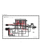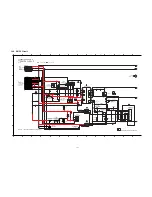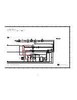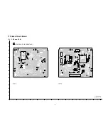
111
18 Appendix Information of Schematic Diagram
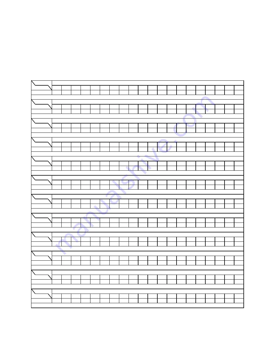
18.1. Voltage & Waveform Chart
Note:
• Indication Voltage Values are in standard values for the unit measured by the DC electronic circuit tester (high-impedance) with
the chassis taken as standard.
Therefore, there may exist some errors in voltage values, depending on the internal impedance of the DC circuit tester.
• Circuit voltage and waveform described herein shall be regarded as reference information when probing defect point because it
may differ from actual measuring value due to difference of Measuring instrument and its measuring condition and product itself.
18.1.1.
CD Servo P.C.B. (1/2)
REF NO.
MODE
1
2
3
4
5
6
7
8
9
10
11
12
13
14
15
16
17
18
19
20
CD PLAY
3.2
1.4
1.4
0.7
0.7
1.2
3.3
1.2
0
3.3
3.2
3.3
0
0.1
1.8
1.8
1.7
3.3
0
1.7
REF NO.
MODE
21
22
23
24
25
26
27
28
29
30
31
32
33
34
35
36
37
38
39
40
CD PLAY
1.7
1.7
1.7
0
3.3
3.3
1.5
3.3
3.3
2.5
8
3.3
0.7
3.2
3.3
0
3.3
3.3
3.3
3.3
REF NO.
MODE
41
42
43
44
45
46
47
48
49
50
51
52
53
54
55
56
57
58
59
60
CD PLAY
3.3
3.3
0
3.3
3.3
0
1.2
1.7
1.7
1.5
1.6
0
1.7
1.7
2
2
1.8
1.9
1.9
1.8
REF NO.
MODE
61
62
63
64
65
66
67
68
69
70
71
72
73
74
75
76
77
78
79
80
CD PLAY
0.2
2.4
0
3.3
1.7
1.7
1
1
1
1.2
1.3
1.7
1.7
1.4
1.4
0.5
0
3.3
3.3
0.9
REF NO.
MODE
81
82
83
84
85
86
87
88
89
90
91
92
93
94
95
96
97
98
99
100
CD PLAY
0
0
0
0
0
0
1.2
3.2
1.5
0
0
3.3
0
1.7
1.7
1.2
3.3
0
0
0
REF NO.
MODE
101
102
103
104
105
106
107
108
109
110
111
112
113
114
115
116
117
118
119
120
CD PLAY
1.2
0
3.3
3.3
3.2
3.3
3.3
3.3
1.5
1.5
1.32
3.3
3.3
0
1.3
1.3
1.3
1.3
3.3
3.3
REF NO.
MODE
121
122
123
124
125
126
127
128
129
130
131
132
133
134
135
136
137
138
139
140
CD PLAY
1.2
0
0
3.3
0
0
0
3.3
0
0
3.3
0
3.2
3.2
0
0.8
0.8
1.6
0
0
REF NO.
MODE
141
142
143
144
CD PLAY
0
1.2
1.4
0.7
REF NO.
MODE
1
2
3
4
5
6
7
8
9
10
11
12
13
14
15
16
17
18
19
20
CD PLAY
3.3
0.7
3.3
0.7
1.4
0
1.4
0.7
3.3
1.4
1.4
0
1.4
3.3
3.3
3.3
3.3
3.3
0
0
REF NO.
MODE
21
22
23
24
25
26
27
28
29
30
31
32
33
34
35
36
37
38
39
40
CD PLAY
0
0
0.1
1.8
1.8
1.7
3.3
0
1.7
1.7
1.7
1.7
0
3.3
3.3
0
3.3
1.5
3.3
0
REF NO.
MODE
41
42
43
44
45
46
47
48
49
50
51
52
53
54
CD PLAY
0
0.6
3.3
1.2
1.2
0
1.2
0.6
3.3
1.2
1.2
0
1.2
0
REF NO.
MODE
1
2
3
4
5
6
7
8
9
10
11
12
13
14
15
16
17
18
19
20
CD PLAY
1.6
9.1
2.5
1.6
2.4
3
3
9
0
0
4.6
4.6
2.6
2.7
2.6
2.7
2
3.1
5
0
IC8001
IC8001
IC8001
IC8051
IC8001
IC8051
SA-AKX73P CD SERVO P.C.B.
IC8001
IC8001
IC8001
IC8001
IC8051
IC8251
Summary of Contents for SA-AKX73P
Page 13: ...13 5 General Introduction 5 1 Media Information ...
Page 14: ...14 6 Location of Controls and Components 6 1 Remote Control Key Button Operation ...
Page 15: ...15 6 2 Main Unit Key Button Operation ...
Page 16: ...16 7 Installation Instructions 7 1 Speaker and A C Connection ...
Page 25: ...25 9 1 2 Main P C B Front Side Fig 2 Main P C B Front Side ...
Page 29: ...29 9 3 D Amp IC Operation Control ...
Page 34: ...34 11 2 Main Components and P C B Locations ...
Page 64: ...64 Step 3 Release 2 tabs Step 4 Remove the Rear Panel ...
Page 80: ...80 ...
Page 82: ...82 ...
Page 124: ...124 ...


