


66
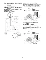
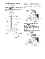
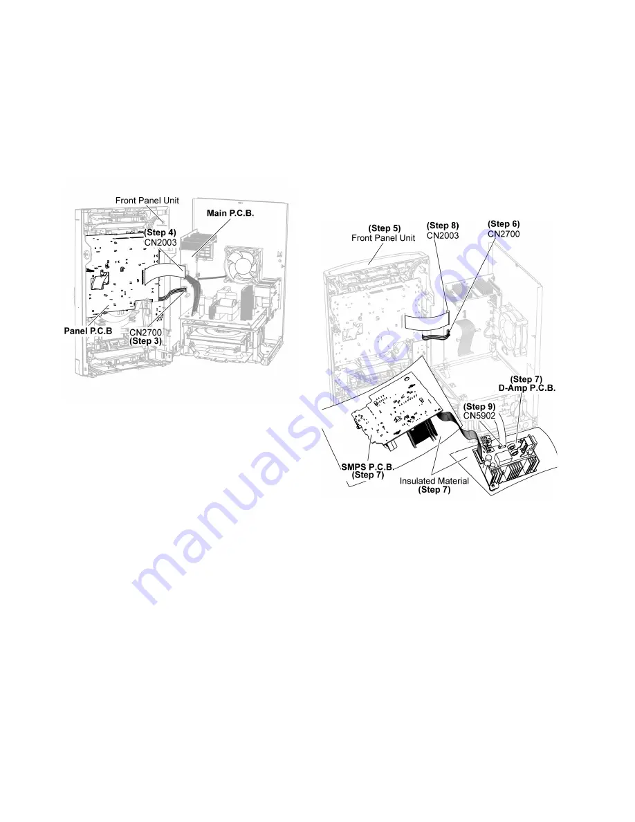
12.3. Checking and Repairing of
Panel P.C.B.
Step 1 Remove Top Cabinet.
Step 2 Remove Front Panel Unit.
Step 3 Attach 5P Cable Wire to the connector (CN2700) on
Main P.C.B..
Step 4 Attach 27P FFC to the connector (CN2003) on Main
P.C.B..
Step 5 Panel P.C.B. can be checked and repaired as diagram
shown.
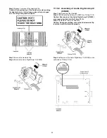
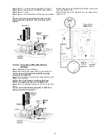
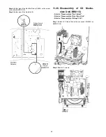
12.4. Checking and Repairing of
SMPS P.C.B.
Step 1 Remove Top Cabinet.
Step 2 Remove Front Panel Unit.
Step 3 Remove D-Amp P.C.B..
Step 4 Remove SMPS P.C.B..
Step 5 Place the Front Panel Unit as diagram shown.
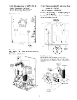
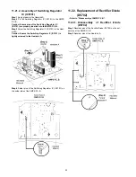
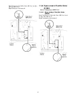
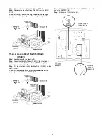
Step 7 Place the SMPS P.C.B., D-Amp P.C.B. on the insulated
material.
Step 8 Attach 27P FFC to the connector (CN2003) on the Main
P.C.B..
Step 9 Attach 9P FFC to the connector (CN5902) on the D-
Amp P.C.B..
Summary of Contents for SA-AKX73P
Page 13: ...13 5 General Introduction 5 1 Media Information ...
Page 14: ...14 6 Location of Controls and Components 6 1 Remote Control Key Button Operation ...
Page 15: ...15 6 2 Main Unit Key Button Operation ...
Page 16: ...16 7 Installation Instructions 7 1 Speaker and A C Connection ...
Page 25: ...25 9 1 2 Main P C B Front Side Fig 2 Main P C B Front Side ...
Page 29: ...29 9 3 D Amp IC Operation Control ...
Page 34: ...34 11 2 Main Components and P C B Locations ...
Page 64: ...64 Step 3 Release 2 tabs Step 4 Remove the Rear Panel ...
Page 80: ...80 ...
Page 82: ...82 ...
Page 124: ...124 ...