


73
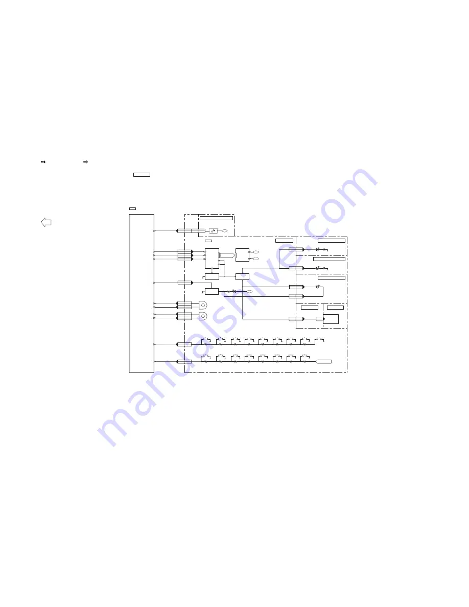
SA-AKX73P SERVO & SYSTEM CONTROL (2/2) BLOCK DIAGRAM
TO SERVO & SYSTEM CONTROL
BLOCK (1/2)
14
14
CN6000
CN2003
MICROPROCESSOR
RFKWMAKX73P
IC2003
FL DATA 82
15
13
CN6000
CN2003
FL CS 83
16
12
CN6000
CN2003
FL CLK 84
FL DOUT
FL CS
FLCLK
17
11
CN6000
CN2003
10
18
CN6000
CN2003
3,4
3,4
CN6200
CN6001
19
9
CN6000
CN2003
KEY2
FL DOUT
2
2
ZJ6600*
CN6004
PW +2.4V
PW +2.4V
2
2
ZJ6700*
CN6005
PW +2.4V
PW +2.4V
FL CS
FLCLK
24
4
CN6000
CN2003
LED DIMMER 38
LED DIMMER
LED DIMMER
3.3V
5V
REMOTE CONTROL
SENSOR
IR6200
QR6001
LED DRIVE
Q6002
LED DRIVE
QR6003
LED DRIVE
RMT 86
RMT
KEY 2 98
KEY2
LED AN
LED AN
18
10
CN6000
CN2003
KEY1
J VOLA
KEY 1 99
KEY1
VOL JOG A 9
J VOLA
11
17
CN6000
CN2003
J VOLB
VOL JOG B 10
J VOLB
MIC SW
POWER
S6002
DIMMER
S6011
MANUAL EQ
S6016
REWIND
S6010
FORWARD
S6009
OPEN/CLOSE
S6015
DISPLAY
S6007
ALBUM/TRACK
S6014
CD
S6006
RADIO
S6005
EXT-IN
S6000
PLAY/PAUSE
S6004
PRESET EQ
S6008
D.BASS
S6012
SUPER WOOFER
S6013
STOP
S6001
VOLUME
VR6000
13
15
CN6000
CN2003
J ROTA
ROTARY JOGA 33
J ROTA
12
16
CN6000
CN2003
J ROTB
ROTARY JOGB 32
J ROTB
ALBUM/TRACK
VR6001
USB
S6003
FROM AUDIO
MAIN P.C.B.
MAIN P.C.B.
SPEAKER
PANEL P.C.B.
TOP BAR LED P.C.B.
BOTTOM BAR LED P.C.B.
D6001,D6002
D6003,D6004
D6600,D6601,D6602
1
1
ZJ6800*
CN6006
2
2
ZJ6800*
CN6006
LED CA
LED CA
6
22
CN2003
CN6000
SUBW LED SUPPLY
1
CN2000
SUBW LED
MEMORY LED P.C.B.
D6800
D6700,D6701,D6702
REMOTE SENSOR P.C.B.
SB-WAKX73
FL DISPLAY
DRIVER
C0HBB0000057
IC6000
FL6000
FL DISPLAY
SG1 ~ SG16
GR1 ~ GR12
DIN
STB
CLK
P0
F-
F+
F-
F+
7
9
8
1
44
1
P2 3
P3 4
NOTE: “ * ” REF IS FOR INDICATION ONLY
: CD AUDIO INPUT SIGNAL LINE
: USB SIGNAL LINE
Summary of Contents for SA-AKX73P
Page 13: ...13 5 General Introduction 5 1 Media Information ...
Page 14: ...14 6 Location of Controls and Components 6 1 Remote Control Key Button Operation ...
Page 15: ...15 6 2 Main Unit Key Button Operation ...
Page 16: ...16 7 Installation Instructions 7 1 Speaker and A C Connection ...
Page 25: ...25 9 1 2 Main P C B Front Side Fig 2 Main P C B Front Side ...
Page 29: ...29 9 3 D Amp IC Operation Control ...
Page 34: ...34 11 2 Main Components and P C B Locations ...
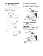
Page 64: ...64 Step 3 Release 2 tabs Step 4 Remove the Rear Panel ...
Page 80: ...80 ...
Page 82: ...82 ...
Page 124: ...124 ...


