


85
I
1
2
3
4
5
6
7
8
9
10
11
12
13
14
K
L
J
M
O
P
N
A
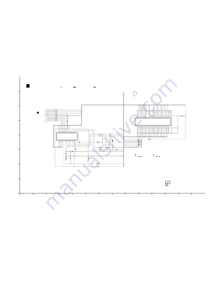
CD SERVO CIRCUIT
SCHEMATIC DIAGRAM - 3
SA-AKX73P CD SERVO CIRCUIT
2/3
1/3
3/3
TO CD SERVO
CIRCUIT (1/3)
P1
H
TO
CD INTERFACE
CIRCUIT (CN7002)
IN SCHEMATIC
DIAGRAM - 19
: CD AUDIO INPUT SIGNAL LINE
: +B SIGNAL LINE
: USB SIGNAL LINE
LB8203
J0JBC0000019
K8208
0.1
CHASSIS
GND
D2
D0
D1
D3
D5
D4
0.1
C8057
D4
D5
D0
PW_3R3V_DIG
D2
D3
0.1
C8052
D1
0.1
C8056
A9
D6
D6
D7
D7
C8053
0.1
C8055
0.1
C8054
0.1
LB8052
J0JHC0000045
0.1
C8042
0.1
C8051
A9
A8
A11
A10
BA0
BA1
A4
A7
A5
A6
A2
A3
DGND
A0
A1
CLK
10K
R8041
NCAS
NWE
NRAS
0.1
C8030
27K
R8258
4.7K
R8259
DAT3_SD
DAT1_SD
DAT2_SD
DAT0_SD
5.6K
R8254
1800P
C8255
1K
R8252
100K
R8265
47K
R8260
R8502
47K
R8503
47K
C8506
0.1
R8504
47K
R8506
47K
R8507
47K
R8505
47K
1200P
C8258
R8256
100
R8257
5.6K
C8253
0.15
F+
6
8
9
7
2
1
10
4
5
3
10
1
FP8251
CLOSE_SW
OPEN_SW
REST_SW
FWD
REV
F-
CMD
DGND
CLK_SD
100
R8261
1.2K
R8264
R8263
1K
C8262
6.3V100
LB8252
J0JHC0000045
1000P
C8256
T-
T+
SPM-
SPM-
SPM+
SPM+
LB8251
J0JHC0000045
3.3K
R8255
10
R8262
C8254
0.015
VREF
C8261
1
C8252
0.01
16V47
C8251
27
5 4
24 25
22
17
19
18
15 16
30
20 21
7
11 10
13
14
12
8 29
9
23
6
3
2
1
26
28
IC8251
C0GBY0000117
5CH MOTOR DRIVER
61
53
12
10 9
11
44
43
45
13
42
5
4
6
7
8
50
49
51
47
46
48
28
31
29 30
24
26
27
25
22
20
18
16
14
15
17
19
21
38
35 36
33 34
37
40 41
39
23
32
3
1
2
52
54
C3ABPG000163
64M SDRAM
IC8051
FOP
TRP
SPOUT
CL8021
CL8014
0
K8004...AKX73
CL8019
0
K8009...AKX73
CL8022
PW_+5V
PW_M+9V
TRVP
PW_3R3V_CD
A5
A7
NC
NC
CKE
CLK
A9
VSS
DQ8
A8
UDQM
A6
A4
VSS
A11
DQ9
DQ10
DQ11
VDDQ
VSSQ
VSS
DQ15
DQ14
DQ12
VSSQ
VDDQ
DQ13
A2
A3
VDD
VDD
DQ1
DQ3
DQ5
A0
A1
VDD
DQ7
CS
/WE
BA1
BA0
DQ6
DQ4
DQ2
VDDQ
VDDQ
LDQM
/RAS
/CAS
VSSQ
VSSQ
DQ0
A10/AP
LDM+
DGND
SPM-
SPM+
LDM-
TRV-
OPEN_SW
CLOSE_SW
REST_SW
TRV+
PGND
LB8501
J0JHC0000045
TP
FWD
TRB_1
VINFC
REGO2
VINSL
REGO1
NC
VINLD
BIAS
MUTE
TRB_2
VINTK
VOTR+
VOSL-
VOSL+
VOFC-
VOFC+
REV
VCC
GND
VOTR-
VCTL
VOTK-
NC
PVCC
VOTK+
VOLD-
VOLD+
GND
GND
K8209
0
Summary of Contents for SA-AKX73P
Page 13: ...13 5 General Introduction 5 1 Media Information ...
Page 14: ...14 6 Location of Controls and Components 6 1 Remote Control Key Button Operation ...
Page 15: ...15 6 2 Main Unit Key Button Operation ...
Page 16: ...16 7 Installation Instructions 7 1 Speaker and A C Connection ...
Page 25: ...25 9 1 2 Main P C B Front Side Fig 2 Main P C B Front Side ...
Page 29: ...29 9 3 D Amp IC Operation Control ...
Page 34: ...34 11 2 Main Components and P C B Locations ...
Page 64: ...64 Step 3 Release 2 tabs Step 4 Remove the Rear Panel ...
Page 80: ...80 ...
Page 82: ...82 ...
Page 124: ...124 ...


