41
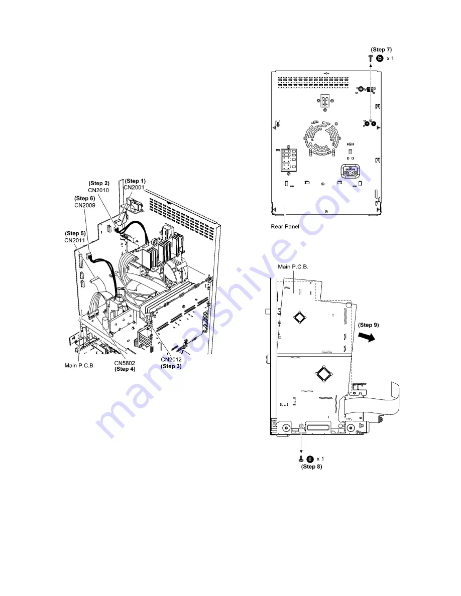
9.12. Disassembly of Main P.C.B.
• Refer to “Disassembly of Top Cabinet”.
• Refer to “Disassembly of Front Panel Assembly”.
Step 1 Detach 9P FFC at the connector (CN2001) on Main
P.C.B..
Step 2 Detach 2P Wire at the connector (CN2010) on Main
P.C.B..
Step 3 Detach 12P FFC at the connecter (CN2012) on Main
P.C.B..
Step 4 Detach 11P Cable Wire at the connecter (CN5802) on
SMPS P.C.B..
Step 5 Detach 17P FFC at the connecter (CN2011) on Main
P.C.B..
Step 6 Detach 2P Wire at the connecter (CN2009) on Main
P.C.B..
Step 7 Remove 1 screw.
Step 8 Remove 1 screw.
Step 9 Detach Main P.C.B. from Rear Panel according to arrow
shown.
Summary of Contents for SA-AKX90PH
Page 13: ...13 5 Location of Controls and Components 5 1 Main Unit Key Button Operation ...
Page 14: ...14 5 2 Remote Control Key Button Operation ...
Page 15: ...15 5 3 Media Information ...
Page 20: ...20 6 4 Self Diagnostic Mode ...
Page 26: ...26 7 2 4 Surround D Amp P C B Fig 4 Surround D Amp P C B D Amp IC IC5900 ...
Page 32: ...32 9 2 Main Components and P C B Locations ...
Page 84: ...84 ...
Page 94: ...94 ...
Page 96: ...96 ...
Page 124: ...124 ...
Page 129: ...129 21 1 2 Packaging ...
Page 130: ...130 ...


