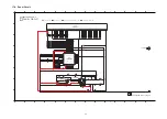
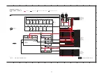
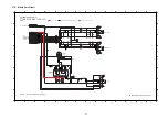
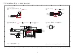
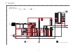
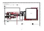
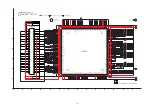
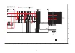
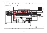
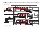
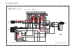
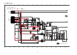
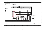
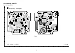
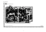
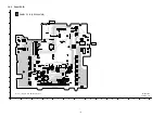
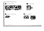
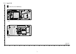
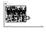
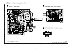
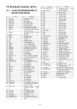
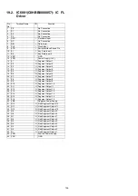
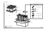
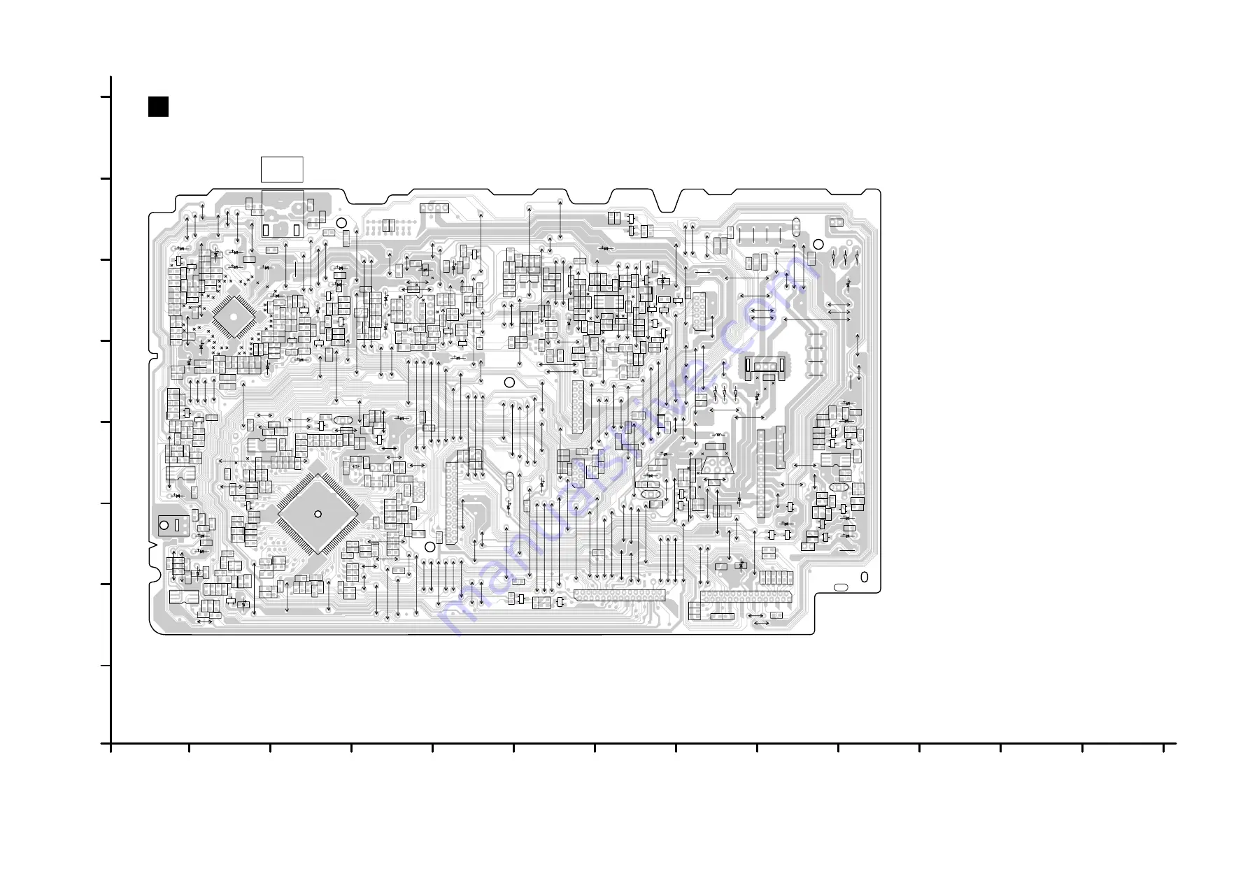
background image

129

18.2. Main P.C.B.

1

1

2

3

4

5

6

7

8

9

A

B

C

D

E

F

G

H

10

1

12

13

B

MAIN P.C.B. (REPX0887AA)    

SA-AKX92PH

MAIN P.C.B.

NOTE: " * " REF IS FOR INDICATION ONLY.

0726AA-3

0726AA-3

LB2007

LB2008
LB2009

C2023

C2022

R2007

R2008

C2015

C2016

R2003

R2004

LB2010

C2008

C2005

C2020

C2012

C2011

C2009

C2010
C2004

C2003

LB2004

LB2003

LB2002

LB2001

LB2000

W5224

R2272

C2189

R2268

R2225

R2224

R2335

TP248

TP247

TP246

TP245

TP244

TP243

TP242

TP241

R2374

R2372

R2373

R2356

R2375

Q2040

Q2041

R2355

Q2037

C2000

R2001

R2002

R2005

R2006

TP26

TP52

TP51

TP50

TP49

TP48

TP47

TP46

TP45

TP44

TP43

TP42

TP41

TP40

TP39

TP38

TP37

TP36

TP35

TP34

TP33

TP32 TP31

TP30

TP29TP28

TP27

TP25

TP24

TP23

TP22

TP21

TP18

TP17

TP15

TP14

TP13
TP12

TP11

TP10

TP09

TP08

TP07

TP06

TP05

TP04

TP03

TP02

TP01

R2020

R2021

R2014 R2016

C2035

C2034

C2033

C2031

C2054

R2012

R2011

R2009

C2026

C2036

C2024

R2010

C2025

C2029

C2053

C2043

C2032

C2049

C2028

R2015

R2013

C2030

C2045

C2067

R2051

C2070

C2072

R2056

C2074

C2076

R2058 C2078

C2080

C2082

R2077

Q2001

R2064

C2092

R2078

C2087

R2063

C2088

C2084

R2062

C2083

R2061

R2060

R2059

C2081

C2079
R2057

C2077
C2075 C2073

R2054

C2068

C2071

R2052

C2044

C2046

C2050

IC2000

TP268

TP264

C2130

R2096

C2102

R2102

R2082

R2067

R2066

C2095

C2094

R2071

R2070

R2085

R2084

R2076

R2074
R2069

R2065

R2073

R2075

R2072

R2068

C2097

C2099

C2106

R2091

R2097

R2106

R2099

R2114

C2115

R2123

D2001

R2218

C2162

R2228

C2163

R2235

C2148

IC2006

D2005

R2157

D2006

R2160

R2182

R2163

R2185

R2165

C2141

R2232

R2198

R2195

R2229

R2197

R2196

C2143

Q2014

R2214

R2221

C2151

R2203

D2008

R2189

Q2011

C2144

C2137

R2174

R2166

R2177
R2164

R2173

R2159

R2178

R2156

R2176

R2154

R2175

R2152

C2129

C2123

R2140 R2136

R2129

R2095

R2126

R2120

R2118

R2098

R2117

R2093

R2115

R2094

R2108

IC2003

R2346

R2344

R2345

R2347

R2343

C2242

W5105

W5119

W5120

W5132

W5165

R2357
C2244

D2028

R2358

Q2039

R2359

R2360

C2248

R2361

Q2038

R2362

C2246

C2247

R2364
R2363

C2245

W5203

W5204

W5206

R2188

QR2002

R2207

R2222

R2223

R2217

R2210

R2204

R2186

R2187

R2190

R2191

C2147

C2149

R2200

R2202

R2199
R2201

R2209

R2208

Q2013

Q2012

C2243

TP258

TP257

TP256

TP255

TP254

TP253

TP252

C2096

C2098

R2083

R2081

R2092

R2090

C2108

R2105

C2107

C2134

R2113

C2116

R2138

R2146

C2127

C2121

R2112

R2128

R2134

C2117

R2137

C2126

C2135

R2150

C2133

R2121

R2127

R2130

R2153

W5214

W5215

R2366
R2365

C2128

R2349

R2350

R2348

Q2050

D2300

W5230

R2261 R2260

R2252

R2253

Q2019

QR2004

TP115

TP113

TP114

TP112

TP111

TP203

TP202

TP201

D2017

R2278

C2191

R2271

C2187

C2229

HEATSINK

D2025

C2216

C2215

R2303

R2309

R2311

R2316

DZ2000

C2235

C2195

C2201

QR2005

Q2023

R2276

R2275

R2274

R2273

C2194

R2248

R2251

R2250

R2247

Q2018

D2015

QR2003

D2014

R2376

W5330

Q2042

R2377

W5343

W5349

W5361

W5367

W5369

W5375

W5385

W5389

W5403

W5444

W5452

W5477

R2329

W5495

W5497

W5503

W5506

W5507

W5508

IC2012

R2379

R2386

R2380

C2251

R2381

R2384

R2388

R2387

R2389

C2254

R2383

R2385

R2378

W5559

D2002

D2003

R2263 R2262

Q2003

R2017

R2018

R2019

R2026

Q2002

Q2021

D2009

C2042

W5572

W5573

W5575

W5584

K2006...PH/PR

QR2006

W5588

C2153

W5589

W5592

W5593

W5594

W5595

W5596

W5598

W5599

W5600

W5601

W5603

W5604

W5606

W5607

CN2006

CN2010

C2021

CN2000

W5222

W5223

C2190

Q2035

R2341

R2339

R2340

R2338

R2337

R2336

R2334

R2333

W5241

CN2003

W5252

W5253

W5254

W5263

W5264

W5265

W5266

W5270

W5271

W5272

W5273

W5279

W5281

W5285

W5286

JK2000

AUX IN

R2079

C2038

C2039

C2057

C2056

C2061

C2090

C2085

C2089

C2093

C2086

C2066

CN2002

(FOR DEBUG)

Q2015

C2150

C2139

X2001

X2000

ZJ2000

W5107

W5121

W5122

W5134

W5146

CN2009

W5163

W5166

W5167

W5168

W5172

W5193

W5195

W5198

W5199

W5200

W5201

W5212

C2146

C2145

C2152

R2107

C2110

C2114

IC2005

W5213

W5216

W5219

W5231

W5124

ZJ2007*

C2188

Q2022

D2022

D2020

D2018

D2021

D2019

D2016

C2234

C2223

L2000

C2226

IC2011

C2198

C2173

K2013

W5298

W5299

W5300

W5301

W5302

W5303

W5306

W5308

W5309

W5312

W5313

K2018

K2019

K2020

K2014

W5331

W5332

W5333

W5335

W5342

W5344

W5345

W5347

W5348

W5351

W5352

W5354

W5355

W5356

W5357

W5359

W5360

W5362

W5365

W5370

W5371

W5372

W5376

W5383

W5384

W5390

W5391

W5392

W5397

W5398

W5399

W5400

W5401

W5404

W5405

W5406

W5407

W5408

W5409

W5411

W5412

W5414

W5415

W5416

W5417

W5418

W5419

W5420

W5421

W5422

W5423

W5425

W5426

W5427

W5429

W5430

W5431

W5433

W5434

W5435

W5436

W5438

W5439

W5440

W5441

W5442

W5450

W5451

W5454

W5455

W5456

W5459

W5460

W5461

W5465

W5466

W5468

W5469

W5470

W5472

W5473

W5474

W5475

W5478

W5481

W5483

W5484

W5486

K2021

W5490

W5491

W5493

W5494

W5500

W5501

W5502

W5504

W5505

W5516

W5521

(TO FAN UNIT)

W5531

W5532

IC2010

W5533

W5535

C2252

C2253

R2382

W5547

W5550

W5552

W5553

W5555

W5556

W5557

W5558

W5570

W5560

W5561

W5562

W5563

W5564

W5565

W5566

W5567

W5569

W5571

K2022

W5576

W5577

W5578

W5579

W5580

W5581

W5583

W5585

W5586

W5587

Q2033

Q2020

K2016

W5590

K2024

C2132

W5597

W5602

W5605

C2249

K2027

R2162

R2193

C2037

C2041

C2047

C2048

C2051

C2055

C2058

C2059

C2060

C2064

C2065

C2119

C2165

C2166

C2168

C2169

C2179

C2180

C2181

C2182

C2183

C2184

C2185

C2186

C2204

C2205

C2240

C2241

CN2004

IC2001

IC2002

IC2009

Q2006

Q2016

Q2017

R2024

R2025

R2028

R2027

R2029

R2030

R2031

R2032

R2034

R2035

R2038

R2039

R2043

R2044

R2045

R2048

R2133

R2238

R2239

R2241

R2242

R2244

R2245

R2254

R2255

R2256

R2257

R2258

R2259

R2264

R2265

R2266

R2267

R2269

R2270

R2290

R2291

R2305

R2308

R2320

R2321

W5609

W5611

C2027

C2040

C2052

C2062

C2063

C2069

C2104

C2105

C2109

C2111

C2112

C2113

C2118

C2122

C2124

C2125

C2131

C2136

C2142

C2196

C2199

C2200

C2238

C2255

C2256

1

2

3

4

CN2001

(TO SUBWOOFER P.C.B. (SB-WAKX92))

1

2

(TO FAN UNIT)

CN2005

6

1

2

3

4

5

CN2008

CN2011

12

2

1

4

3

6

5

8

7

10

9

11

D2004

D2007

CA

A
A

D2010

D2032

1

4

5

8

IC2004

K2003..AKX92

K2011

B

C

E

Q2004

B

C

E

Q2005

B

C

E

Q2007

B

C

Q2008

E

B

C

E

Q2009

B

C

E

Q2010

B

C

E

Q2024

B

C

E

Q2025

B

C

E

Q2031

B

C

E

QR2000

B

C

E

QR2001

R2033

R2036

R2037

R2040

R2041

R2042

R2049

R2089

R2103

R2110

R2111

R2119

R2124

R2125

R2131

R2132

R2135

R2145

R2147

R2148

R2149

R2151

R2155

R2161

R2167

R2170

R2171

R2172

R2179

R2180

R2181

R2183

R2184

R2192

R2281

R2286

R2287

R2288

R2289

R2390

R2392

R2393

R2394

R2395

R2396

R2397

R2168

R2169

C2192

C2193

C2257

C2258

K2025

R2246

R2294

R2295

PbF

B

C

E

B

C

E

B

C

E

B

C

E

B

C

E

B

C

E

B

C

E

B

C

E

B

C

E

B

C

E

B

C

E

B

C

E

B

C

E

B

C

E

B

C

E

B

C

E

B

C

E

B

C

E

B

C

E

B

C

E

B

C

E

B

C

E

B

C

E

B

C

E

B

C

E

CA

A

A

B

C

E

B

C

E

B

C

E

B

C

E

52

50

45

40

39

35

30

27

26

20

14

13

10

5

1

1

4

5

8

1

5

10

15

20

25

26

30

35

40

45

50

51

55

60

65

70

75

76

80

85

90

95

100

6

4

3
1

6

4

3

1

1

4

5

8

1

2

1

2

3

4

5

7

6

8

9

1

2

3

4

5

6

7

8

9

10

11

12

13

14

15

16

17

18

19

20

21

22

23

24

25

26

27

28

29

30

1

2

3

4

5

6

7

8

9

10

11

12

13

14

15

16

17

18

19

20

21

22

23

24

25

26

27

28

29

30

3-RCH

2-LCH

1-GND

4-GND

1

2

5

6

3

4

1

2

3

3

1

2

1

2

3

4

5

6

7

8

9

10

11

12

13

14

15

16

17

18

19

20

21

22

23

25

24

27

26

1

4

5

8

15

1

2

3

4

5

6

7

8

9

10

11

12

13
14

1

2

3

4

5

1

2

3

1

2

3

4

5

6

7

8

9

10

11

12

13

15

14

17

16

1

4

5

8

1

4

5

8

1

4

5
8

Summary of Contents for SA-AKX92PH

Page 1: ...aser Diode 7 2 3 Service caution based on Legal restrictions 8 2 4 Handling Precautions for Traverse Unit 9 3 Service Navigation 11 3 1 Service Information 11 4 Specifications 12 5 Location of Controls and Components 13 5 1 Main Unit Key Button Operation 13 5 2 Remote Control Key Button Operation 14 5 3 Media Information 15 6 Self Diagnostic and Special Mode Setting 16 6 1 Cold Start 16 6 2 Doctor...

Page 2: ... 1 Checking and Repairing of Main P C B 74 11 2 Checking and Repairing of D Amp P C B 74 11 3 Checking and Repairing of Surround D Amp P C B 75 11 4 Checking and Repairing of Panel P C B 75 11 5 Checking and Repairing of Jupiter P C B 76 11 6 Checking and Repairing of SMPS P C B 77 11 7 Checking and Repairing of CD Servo P C B 78 12 Voltage Waveform Chart 79 12 1 CD Servo P C B 79 12 2 Main P C B ...

Page 3: ...el with a 0 15µF capacitors between each exposed metallic part on the set and a good earth ground such as a water pipe as shown in Figure 1 3 Use an AC voltmeter with 1000 ohms volt or more sensitivity to measure the potential across the resistor 4 Check each exposed metallic part and measure the voltage at each point 5 Reverse the AC plug in the AC outlet and repeat each of the above measurements...

Page 4: ...try The protection circuitry may have operated if either of the following conditions are noticed No sound is heard when the power is turned on Sound stops during a performance The function of this circuitry is to prevent circuitry damage if for example the positive and negative speaker connection wires are shorted or if speaker systems with an impedance less than the indicated rated impedance of t...

Page 5: ...A2 K2CQ2CA00007 AC CORD A3 RQTX1300 M O I BOOK Sp PCB10 REPX0886G SMPS P C B RTL PCB11 REPX0886G VOLTAGE SELECTOR P C B RTL DZ5701 ERZV10V511CS ZNR S5701 K0ABCA000007 SW VOLTAGE SELECTOR L5701 G0B932H00002 LINE FILTER T5701 G4DYZ0000049 SWITCHING TRANSFORMER T5751 ETS19AB2E6AG SWITCHING TRANSFORMER T6000 G4DYA0000214 SUB TRANSFORMER PC5701 B3PBA0000503 PHOTO COUPLER PC5702 B3PBA0000503 PHOTO COUPL...

Page 6: ...f the assembly 3 Use only a grounded tip soldering iron to solder or unsolder ES devices 4 Use only an anti static solder removal device Some solder removal devices not classified as anti static ESD protected can generate electrical charge sufficient to damage ES devices 5 Do not use freon propelled chemicals These can generate electrical charges sufficient to damage ES devices 6 Do not remove a r...

Page 7: ...ation power from pickup 100 µW VDE Laser radiation from the pickup unit is safety level but be sure the followings 1 Do not disassemble the pickup unit since radiation from exposed laser diode is dangerous 2 Do not adjust the variable resistor on the pickup unit It was already adjusted 3 Do not look at the focus lens using optical instruments 4 Recommend not to look at pickup lens for a long time ...

Page 8: ...is used Definition The letter of PbF is printed on the PCB using the lead free solder To put lead free solder it should be well molten and mixed with the original lead free solder Remove the remaining lead free solder on the PCB cleanly for soldering of the new IC Since the melting point of the lead free solder is higher than that of the normal lead solder it takes the longer time to melt the lead...

Page 9: ... Special care must be taken avoid caution to electrostatic discharge damage when servicing the laser diode 1 Do not give a considerable shock to the optical pickup unit as it has an extremely high precise structure 2 To prevent the laser diode from the electrostatic discharge damage the flexible cable of the optical pickup unit removed should be short circuited with a short pin or a clip 3 The fle...

Page 10: ...ctric ity in the working environment Proceed servicing works under the working environment where grounding works is completed 2 4 2 1 Worktable grounding 1 Put a conductive material sheet or iron sheet on the area where the optical pickup is placed and ground the sheet 2 4 2 2 Human body grounding 1 Use the anti static wrist strap to discharge the static electricity form your body ...

Page 11: ... not the drawing reference numbers If the circuit is changed or modified this information will be followed by supplement service manual to be filed with original service manual CD Mechanism Unit BRS1C 1 This model uses CD Mechanism Unit BRS1C Micro processor 1 The following components are supplied as an assembled part Micro processor IC IC2003 RFKWMAKX92M0 Speaker System 1 This model uses Speaker ...

Page 12: ...t left channel FR Front right channel Q USB SECTION USB Port USB standard USB 2 0 full speed Media file format support MP3 mp3 USB device file system FAT12 FAT16 FAT32 USB Port power 500 mA max Bit Rate 16 kbps to 320 kbps playback USB recording Bit Rate 128 kbps 192 kbps 320 kbps USB recording speed 1x 4x CD only recording file format MP3 mp3 Q INTERNAL MEMORY SECTION Memory Memory size 4 GB Memo...

Page 13: ...13 5 Location of Controls and Components 5 1 Main Unit Key Button Operation ...

Page 14: ...14 5 2 Remote Control Key Button Operation ...

Page 15: ...15 5 3 Media Information ...

Page 16: ... Cold Start Here is the procedure to carry out cold start or initialize to shipping mode 1 Unplug AC power cord 2 Press hold POWER button 3 Plug AC power cord while POWER button being pressed FL Display will show _ _ _ _ _ _ _ _ 4 Release POWER button ...

Page 17: ...tor Mode 1 In CD Mode Press button on main unit follow by 4 and 7 on remote control 2 To exit press OK button on remote control or press POWER I button on main unit or remote control In Doctor Mode 1 Press 2 button on remote control Display 1 Display 2 To check the firmware version for Jupiter Microprocessor IC Display 1 will display for 2 secs followed by display 2 Micro processor Version ...

Page 18: ...l increment by one When reach 9999 will change to 0000 Cancellation Display BRS1C Reliability Test Loading To determine CD Mechanism Unit BRS1C Open Close operation Note Refer to Section 6 3 Fig 2 for process flow The counter will increment by one When reach 9999 will change to 0000 Cancellation Display BRS1C Reliability Test Traverse To determine CD Mechanism BRS1C Access Inner Outer disc operati...

Page 19: ...Fig 2 Reliability Test Traverse Fig 3 Reliability Test Combination OPEN Operation OPEN wait fot 1 s CLOSE Operation CLOSE wait for 4s Count up First Track Access First Track Play 5 s Last Track Access Last Track Play 5 s Count up First Track Access First Track Play 10 s Last Track Access Last Track Play 10 s Open Operation Open wait for 1 s CLOSE Operation Count up ...

Page 20: ...mote control To check for USB error Codes Error Code History USB Error Code History Software Display Version l To check for following 1 System Version 2 Jupiter Micro processor Version 3 Opecon Version In CD Mode 1 Press and hold button on main unit for 2 secs 2 Do not release button press and hold on the remote control for 2 secs 3 To exit press POWER button on main unit History number Display of...

Page 21: ...hanism Error Code Table CD Mechanism Unit BRS1C Error Code Diagnostic Contents Descriptionof error Automatic FL Display Remarks CD H15 CD Open Abnormal During operation POS_SW_R On fail to be detected with 4 sec Error No shall be clear by force or during cold start Press on main unit for next error CD H16 CD Closing Abnormal During operation POS_SW_CEN On fail to be detected with 4 sec Error No sh...

Page 22: ... OPEN CLOSE and keys for 5 sec Step 4 The display will show upon entering into this mode Note OPEN CLOSE button is invalid and the main unit displays LOCKED while the lock function mode is entered 6 6 2 Cancellation Step 1 To cancel only can be triggered in CD Mode and Volume 19 Step 2 Select to any mode function press and hold OPEN CLOSE key and follow by key pressed within 0 5 sec Step 3 Hold bo...

Page 23: ...D Amp IC Check VDD SS supply at pin 4 20 of D Amp IC Check pin 1 OSC pin 23 MODE of D Amp IC Check pattern crack and solderability Refer to section 7 2 3 Fig 3 D Amp P C B Refer to section 7 2 4 Fig 4 Surround D Amp P C B then F61 2 D AMP circuit 2b D AMP IC IC5900 defective 1b Check output IC Pin 10 14 which have DC Voltage DC voltage of 30V detected at speaker output Set can ON 1 Transformer T57...

Page 24: ...P C B Fig 1 SMPS P C B Thermistor TH5860 Photocoupler PC5720 AC Inlet P5701 Fuse F1 Photocoupler PC5702 PC5799 Switching Regulator IC IC5701 Switching Regulator IC IC5799 Transformer T5701 Rectifier Diode D5801 D5802 Connector CN5802 ...

Page 25: ...25 7 2 2 Main P C B Fig 2 Main P C B Connector ZJ2007 Voltage Regulator IC IC2010 DC DC Converter IC IC2011 ...

Page 26: ...26 7 2 3 D Amp P C B Fig 3 D Amp P C B Audio Digital Amp IC IC5400 Audio Digital Amp IC IC5200 Audio Digital Amp IC IC5000 Audio Digital Amp IC IC5300 ...

Page 27: ...27 7 2 4 Surround D Amp P C B Fig 4 Surround D Amp P C B Audio Digital Amp IC IC5900 ...

Page 28: ... IC No MODE_DA MUTE_F Digital AMP IC mode status 1 L X OFF 0V 2 H H Mute 2 5V 3 H L Operating 5V Table 2 Digital AMP IC Mode Status Note Standby OFF condition of D AMP IC is available activated only during the following event Switching of Frequency Hoping power off and start up when the unit is undergoing the transition from standby to normal operation mode B F_HOP is used to control the D AMP ope...

Page 29: ...60 1450 L 301 1460 1540 H 350 1550 1710 L 301 Table 4 F_HOP Control during 10 kHz Step Note During activating the 3 control pins namely MUTE_F MUTE_A and MODE_DA must be used to cover the Pop sound cause by F HOP switching ...

Page 30: ...30 8 Service Fixture Tools 8 1 Service Tools and Equipment Prepare service tools before process service position Service Tools Remarks Main P C B ZJ2007 SMPS P C B CN5802 REXX1206 15P Cable Wire ...

Page 31: ... List as described in the ser vice manual Select items from the following indexes when disassembly or replacement are required Disassembly of Top Cabinet Disassembly of Tuner P C B Disassembly of Front Panel Unit Disassembly of Panel P C B Disassembly of Remote Sensor P C B Disassembly of Jupiter P C B Disassembly of USB P C B Disassembly of Music Port P C B Disassembly of CD Lid Disassembly of Ma...

Page 32: ... Main P C B 9 14 D Amp P C B 9 28 Surround D Amp P C B 9 19 SMPS P C B 9 13 Voltage Regulator IC IC2010 9 27 Voltage Selector P C B 9 15 Audio Digital Amp IC IC5000 9 16 Audio Digital Amp IC IC5400 9 17 Audio Digital Amp IC IC5200 9 18 Audio Digital Amp IC IC5300 9 4 Tuner P C B 9 5 Front Panel Unit 9 7 Panel P C B 9 8 Remote Sensor P C B 9 29 Audio Digital Amp IC IC5900 9 10 Music Port P C B 9 6 ...

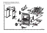
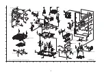
Page 33: ...33 9 2 Main Components and P C B Locations ...

Page 34: ...s Step 3 Slightly pull both side of Top Cabinet outwards as arrow shown Step 4 Slightly lift up both side of Top Cabinet in an outward direction as shown Step 5 Remove Top Cabinet Caution During assembling ensure that the Top Cabinet catches are properly located into Front Panel Unit as shown ...

Page 35: ...1 screw Step 2 Detach 9P FFC at the connector CN51 on Tuner P C B Step 3 Remove Tuner P C B 9 5 Disassembly of Front Panel Unit Refer to Disassembly of Top Cabinet Step 1 Detach 30P FFC at the connector CN2000 on Jupiter P C B Step 2 Detach 30P FFC at the connector CN2003 on Main P C B ...

Page 36: ...inwards slightly at the Bottom Chassis and release tab at left side of Front Panel Unit Step 4 Release tab at bottom Step 5 Push inwards slightly at the Bottom Chassis and release tab at right side of Front Panel Unit ...

Page 37: ...r to Disassembly of Front Panel Unit Step 1 Detach 30P FFC at the connector CN601 on Jupiter P C B Caution Keep the 30P FFC in safe place place it back dur ing assembling Step 2 Remove 2 screws Step 3 Detach 7P connector CN503 on Jupiter P C B from 7P connector CN6003 on USB P C B Step 4 Remove Jupiter Unit ...

Page 38: ...e Jupiter P C B 9 7 Disassembly of Panel P C B Refer to Disassembly of Top Cabinet Refer to Disassembly of Front Panel Unit Refer to Disassembly of Jupiter P C B Step 1 Remove the Volume Knob Step 2 Remove the Track Knob Step 3 Remove 8 screws ...

Page 39: ...se catches by following the sequences 1 6 Step 6 Lift up Panel P C B Step 7 Desolder 12pins at ZJ6002A on Panel P C B Step 8 Remove the Panel P C B Caution During assembling ensure that Panel P C B is seated properly through the guides fully catched ...

Page 40: ...f item 9 7 Step 1 Remove Remote Sensor P C B Caution During assembling ensure that Sensor P C B is properly inserted fully connected to Panel P C B 9 9 Disassembly of USB P C B Refer to Disassembly of Top Cabinet Refer to Disassembly of Front Panel Unit Refer to Disassembly of Jupiter P C B Step 1 Remove 2 screws Step 2 Lift up USB unit Step 3 Release 2 catches Step 4 Remove the USB P C B ...

Page 41: ...ove 2 screws Step 3 Remove Ground Plate Caution Place the Ground Plate in safe place place it back during assembly Step 4 Release 2 catches Step 5 Lift up Music Port P C B Caution During assembling ensure that Music Port P C B is properly located fully catched onto Front Panel Step 6 Desolder 12 pins ZJ6002 on Music Port P C B Step 7 Remove Music Port P C B ...

Page 42: ...Cable Wire is dressed into the outer slot properly 9 11 Disassembly of CD Lid Refer to Disassembly of Top Cabinet Refer to Disassembly of Front Panel Unit Step 1 Remove the spring as arrow shown in order of sequence 1 to 3 Caution During assembling ensure that the spring is assembly at right position Step 2 Remove CD Lid as arrow shown ...

Page 43: ... the connector CN2005 on Main P C B Step 3 Detach 6P Cable Wire at the connector CN2008 on Main P C B Step 4 Detach 9P FFC at the connector CN2010 on Main P C B Step 5 Detach 12P FFC at the connector CN2011 on Main P C B Step 6 Detach 15P Cable Wire at the connector CN5802 on SMPS P C B Step 7 Remove 1 screw Step 8 Remove 1 screw Step 9 Detach Main P C B from Rear Panel according to arrow shown ...

Page 44: ...en inserted to locators 9 13 Replacement of Voltage Regu lator IC IC2010 Refer to Disassembly of Main P C B 9 13 1 Disassembly of Voltage Regulator IC IC2010 Step 1 Desolder pins of the Voltage Regulator IC IC2010 on the solder side of Main P C B Step 2 Remove 1 screw Step 3 Remove the Voltage Regulator IC IC2010 from the Main P C B Caution Avoid touching the Heatsink due to its high tem perature ...

Page 45: ... Regulator IC IC2010 to the Heat sink Caution Ensure the Voltage Regulator IC IC2010 is tightly screwed to the Heatsink Step 4 Solder pins of the Voltage Regulator IC IC2010 on the solder side of Main P C B 9 14 Disassembly of D Amp P C B Refer to Disassembly of Top Cabinet Refer to Disassembly of Front Panel Unit Step 1 Remove 2 screws Step 2 Twist the Wire Holder to release 6P Cable Wire Step 3 ...

Page 46: ...ew Step 5 Slightly lift up remove D Amp Unit as arrow shown Caution During assembling ensure that D Amp Bracket is seated on the locator of Inner Chassis properly Step 6 Detach 17P FFC at the connector CN5050 on D Amp P C B ...

Page 47: ...IC5000 Refer to Disassembly of D Amp P C B Step 1 Flip over D Amp P C B Step 2 Desolder pins of the Audio Digital Amp IC IC5000 on the solder side of D Amp P C B Step 3 Remove 1 screw Step 4 Remove TR Spring in the direction of arrow shown Step 5 Remove Audio Digital Amp IC IC5000 Caution During replacement of the part avoid touching the heatsink it may lead to injuries ...

Page 48: ...Caution Ensure pins of the Audio Digital Amp IC IC5000 are properly seated and soldered on D Amp P C B 9 16 Replacement of Audio Digital Amp IC IC5400 Refer to Disassembly of D Amp P C B Step 1 Flip over D Amp P C B Step 2 Desolder pins of the Audio Digital Amp IC IC5400 on the solder side of D Amp P C B Step 3 Remove 1 screw Step 4 Remove TR Spring in the direction of arrow shown Step 5 Remove Au...

Page 49: ...Caution Ensure pins of the Audio Digital Amp IC IC5400 are properly seated and soldered on D Amp P C B 9 17 Replacement of Audio Digital Amp IC IC5200 Refer to Disassembly of D Amp P C B Step 1 Flip over D Amp P C B Step 2 Desolder pins of the Audio Digital Amp IC IC5200 on the solder side of D Amp P C B Step 3 Remove 1 screw Step 4 Remove TR Spring in the direction of arrow shown Step 5 Remove Au...

Page 50: ...f TR Spring Caution Ensure pins of the Audio Digital Amp IC IC5200 are properly seated and soldered on D Amp P C B 9 18 Replacement of Audio Digital Amp IC IC5300 Refer to Disassembly of D Amp P C B Step 1 Flip over D Amp P C B Step 2 Desolder pins of the Audio Digital Amp IC IC5300 on the solder side of D Amp P C B Step 3 Remove 1 screw Step 4 Remove TR Spring in the direction of arrow shown Step...

Page 51: ...tal Amp IC Step 4 Use a blower to remove the minute particles after the screwing of TR Spring Caution Ensure pins of the Audio Digital Amp IC IC5300 are properly seated and soldered on D Amp P C B 9 19 Disassembly of SMPS P C B Refer to Disassembly of Top Cabinet Refer to Disassembly of Front Panel Unit Refer to Disassembly of D Amp P C B Step 1 Remove 1 screw Step 2 Remove 3 screws Step 3 Detach ...

Page 52: ... the SMPS P C B and position it according to dia gram shown Step 7 Position SMPS P C B on the insulated material Step 8 Desolder 2 Wire pins TL7 Black TL8 Red wires pin Step 9 Remove SMPS P C B 9 20 Replacement of Regulator IC IC5701 Refer to Disassembly of SMPS P C B 9 20 1 Disassembly of Regulator IC IC5701 Step 1 Desolder pins of the Regulator IC IC5701 on the sol der side of SMPS P C B ...

Page 53: ... to injuries 9 20 2 Assembly of Regulator IC IC5701 Step 1 Apply grease to the Heatsink A Step 2 Fix the Regulator IC IC5701 to the SMPS P C B Caution Ensure pins of the Regulator IC IC5701 are prop erly inserted and soldered on SMPS P C B Step 3 Screw the Regulator IC IC5701 to the Heatsink A Caution Ensure the Regulator IC IC5701 is tightly screwed to the Heatsink A ...

Page 54: ... side of SMPS P C B 9 21 Replacement of Rectifier Diode D5702 Refer to Disassembly of SMPS P C B 9 21 1 Disassembly of Rectifier Diode D5702 Step 1 Desolder pins of the Rectifier Diode D5702 on the sol der side of SMPS P C B Step 2 Desolder pins of the Heatsink A ...

Page 55: ...bly of Rectifier Diode D5702 Step 1 Apply grease to the Heatsink A Step 2 Screw the Rectifier Diode D5702 to the Heatsink A Caution Ensure the Rectifier Diode D5702 is tightly screwed to the Heatsink A Step 3 Fix the Heatsink A with Rectifier Diode D5702 on SMPS P C B in the direction of arrow Caution Ensure the Heatsink A with Rectifier Diode D5702 are properly seated on SMPS P C B Step 4 Screw t...

Page 56: ...SMPS P C B 9 22 Replacement of Rectifier Diode D5801 Refer to Disassembly of SMPS P C B 9 22 1 Disassembly of Rectifier Diode D5801 Step 1 Desolder pins of the Rectifier Diode D5801 on the sol der side of SMPS P C B Step 2 Remove 1 screw at Rectifier Diode D5801 Step 3 Remove the Rectifier Diode D5801 from the SMPS P C B Caution Avoid touching the Heatsink B due to its high temperature after prolo...

Page 57: ...rewed to the Heatsink B Step 4 Solder pins of the Rectifier Diode D5801 on the solder side of SMPS P C B 9 23 Replacement of Rectifier Diode D5802 Refer to Disassembly of SMPS P C B 9 23 1 Disassembly of Rectifier Diode D5802 Step 1 Desolder pins of the Rectifier Diode D5802 on the sol der side of SMPS P C B Step 2 Remove 1 screw at Rectifier Diode D5802 Step 3 Remove the Rectifier Diode D5802 fro...

Page 58: ...ed to the Heatsink B Step 4 Solder pins of the Rectifier Diode D5802 on the solder side of SMPS P C B 9 24 Replacement of Rectifier Diode D5803 Refer to Disassembly of SMPS P C B 9 24 1 Disassembly of Rectifier Diode D5803 Step 1 Desolder pins of the Rectifier Diode D5803 on the sol der side of SMPS P C B Step 2 Remove 1 screw at Rectifier Diode D5803 Step 3 Remove the Rectifier Diode D5803 from t...

Page 59: ...ifier Diode D5803 is tightly screwed to the Heatsink B Step 4 Solder pins of the Rectifier Diode D5803 on the solder side of SMPS P C B 9 25 Disassembly of CD Mecha nism Unit BRS1C Refer to Disassembly of Top Cabinet Refer to Disassembly of Front Panel Unit Refer to Disassembly of D Amp P C B Step 1 Detach 15P Wire at the connector CN5802 on SMPS P C B Step 2 Detach 12P FFC at the connector CN2011...

Page 60: ...move 3 screws Step 6 Detach Voltage Selector P C B from Rear Panel as arrow shown Step 7 Lift up SMPS Inner Chassis Unit Caution During assembling ensure that SMPS Inner Chassis is catched onto Rear Panel properly ...

Page 61: ...tor CN7002 on CD Servo P C B Step 11 Remove CD Mechanism Unit BRS1C 9 26 Disassembly of Rear Panel Refer to Disassembly of Top Cabinet Refer to Disassembly of Tuner P C B Step 1 Remove 8 screws Step 2 Detach 2P Wire at the connector CN2006 on Main P C B Step 3 Detach Voltage Selector P C B from Rear Panel as arrow shown ...

Page 62: ...catch between the SMPS Inner Chassis Unit the Rear Panel Step 5 Release 2 tabs Step 6 Remove Rear Panel 9 27 Disassembly of Voltage Selec tor P C B Refer to Disassembly of Top Cabinet Step 1 Remove 1 screw Step 2 Detach Voltage Selector P C B from Rear Panel ...

Page 63: ...C B Step 4 Remove Voltage Selector P C B 9 28 Disassembly of Surround D Amp P C B Refer to Disassembly of Top Cabinet Step 1 Remove 3 screws Step 2 Detach 6P Cable Wire at the connector CN2008 on Main P C B Step 3 Detach 12P FFC at the connector CN5902 on Sur round D Amp P C B ...

Page 64: ... assembling ensure that Surround D Amp Unit is catched onto Rear Panel properly Step 5 Remove 1 screw Step 6 Remove Surround D Amp P C B as arrow shown Caution During assembling ensure that Surround D Amp P C B is inserted to the catches seated at the locator properly ...

Page 65: ...udio Digital Amp IC IC5900 Step 1 Desolder pins of the Regulator IC IC5900 on the sol der side of D Amp P C B Step 2 Release 2 catches of Heatsink Clip Caution During releasing of 2 catches avoid touching the Heatsink due to high temperature Step 3 Remove Heatsink Clip Step 4 Remove Audio Digital Amp IC IC5900 ...

Page 66: ...C IC5900 on D Amp P C B Caution Ensure pins of the Audio Digital Amp IC IC5900 are properly seated on D Amp P C B Step 3 Fix Heatsink Clip to the Heatsink Caution During assembling ensure that Heatsink Clip is catched onto Heatsink properly Step 4 Solder pins of the Audio Digital Amp IC IC5900 on the solder side of D Amp P C B ...

Page 67: ...tical Pickup Unit Note 1 When the optical pickup unit is defective the overall traverse unit needs replacement 2 Please note that appropriate actions need to be taken to prevent static damage 3 Ensure that the circuit is open before assembly BRS1 to the main set Step 1 Use a pin to Slide the Traverse Slide Plate until it come to a stop Step 2 Slide the tray out fully Step 3 Release the catches rem...

Page 68: ...erse Slide Plate to the end Step 5 Detach 5P FFC at the connector CN7003 on CD Servo P C B Step 6 Lift the Traverse Unit by approximately 45 Step 7 Slide out the traverse unit as arrow shown Caution Avoid touching the surface of the Optical Pickup Unit ...

Page 69: ...69 10 2 Assembly of Traverse Unit Step 1 Release the guide as shown slide the Traverse Slide Plate to the end Step 2 Slot the Traverse Unit at approximately 45 into the mecha chassis as arrow shown ...

Page 70: ...e Groove Step 4 Slide Traverse Slide Plate to lock the Traverse Unit as shown Step 5 Connect 5P FFC at the connector CN7003 on CD Servo P C B Step 6 Slide the Traverse Slide Plate unit it stop at the Guide Step 7 Slot the Tray into the guides as Picture shown ...

Page 71: ...Slide the tray in fully 10 3 Disassembly of CD Servo P C B Refer to Disassembly of CD Mechanism Unit BRS1C Refer to Replacement of Traverse Unit Caution It is required to short the circuit Step 1 Solder the 3 solder points Caution 1 Avoid touching the surface of the Optical Pickup Unit ...

Page 72: ...emove 3 screws Step 3 Desolder 4 pins Step 4 Detach 5P FFC at the connector CN7003 on CD Servo P C B Step 5 Slightly lift up the CD Servo P C B Step 6 Flip the CD Servo P C B Step 7 Detach 24P FPC at the connector CN7001 on CD Servo P C B Step 8 Remove CD Servo P C B ...

Page 73: ...73 Step 9 Ground the 24P FFC with a short pin ...

Page 74: ... Section 9 11 1 Checking and Repairing of Main P C B Step 1 Remove Top Cabinet Step 2 Main P C B can be checked repaired at its original position 11 2 Checking and Repairing of D Amp P C B Step 1 Remove Top Cabinet Step 2 D Amp P C B can be checked repaired at its original position ...

Page 75: ... C B Step 5 Surround D Amp P C B can be checked and repaired as diagram shown Caution Insulated Material is required to insulate Sur round D Amp P C B from other parts 11 4 Checking and Repairing of Panel P C B Step 1 Remove Top Cabinet Step 2 Remove Front Panel Unit Step 3 Attach 30P FFC to the connector CN2000 on Main P C B Step 4 Attach 30P FFC to the connector CN2003 on Main P C B Step 5 Panel...

Page 76: ...of Jupiter P C B can be checked and repaired as diagram shown 11 5 2 Checking and Repairing side A of Jupiter P C B Step 1 Remove Top Cabinet Step 2 Remove Front Panel Unit Step 3 Remove the Jupiter P C B Step 4 Position Front Panel Unit as shown Step 5 Attach 30P FFC to the connector CN2000 on Main P C B Step 6 Attach 30P FFC to the connector CN2003 on Main P C B Step 7 Position Jupiter P C B on ...

Page 77: ... C B on the insulated material Step 9 Attach 30P FFC to the connector CN2000 on Main P C B Step 10 Attach 30P FFC to the connector CN2003 on Main P C B Step 11 Attach 17P FFC to the connector CN5050 on D Amp P C B Step 12 Attach 6P Cable Wire to the connector CN2008 on Main P C B Step 13 Attach 12P FFC to the connector CN5902 on Sur round D Amp P C B Step 14 Extend the Cable Wire with extension Ca...

Page 78: ...ulated materials Step 10 Attach 30P FFC to the connector CN2000 on Main P C B Step 11 Attach 30P FFC to the connector CN2003 on Main P C B Step 12 Attach 17P FFC to the connector CN5050 on D Amp P C B Step 13 Attach 15P Cable Wire to the connector CN5802 on SMPS P C B Step 14 Latch D Amp P C B onto Inner Chassis Step 15 Attach 6P Cable Wire to the connector CN5801 on SMPS P C B Step 16 Attach 6P C...

Page 79: ...scribed herein shall be regarded as reference information when probing defect point because it may differ from actual measuring value due to difference of Measuring instrument and its measuring condition and product itself 12 1 CD Servo P C B REF NO MODE 1 2 3 4 5 6 7 8 9 10 11 12 13 14 15 16 17 18 19 20 CD PLAY 1 6 0 1 6 0 0 0 0 0 0 7 7 4 4 3 5 3 6 3 6 3 5 3 8 3 7 3 6 7 7 0 REF NO MODE 21 22 23 2...

Page 80: ...3 3 3 3 3 0 0 0 3 3 3 3 3 0 0 0 0 0 0 0 REF NO MODE 61 62 63 64 65 66 67 68 69 70 71 72 73 74 75 76 77 78 79 80 POWER ON 0 0 0 0 0 0 0 0 3 3 0 0 0 3 3 3 3 3 3 3 3 3 3 3 3 0 0 STANDBY 0 0 0 0 0 0 0 0 3 3 0 0 0 3 3 3 3 3 3 3 3 3 3 3 3 0 0 REF NO MODE 81 82 83 84 85 86 87 88 89 90 91 92 93 94 95 96 97 98 99 100 POWER ON 0 3 3 3 3 0 0 3 3 3 3 3 3 3 3 0 0 0 0 6 0 9 3 3 0 0 9 3 3 2 6 3 3 STANDBY 0 3 3 3...

Page 81: ... 0 2 6 1 0 8 TUNER 0 5 9 0 7 5 12 0 8 1 16 1 0 16 1 0 0 0 7 0 2 6 1 0 8 REF NO MODE E C B E C B E C B E C B E C B POWER ON 0 3 3 0 16 4 16 5 11 6 0 0 3 1 4 2 4 2 0 0 3 2 0 TUNER 0 3 3 0 16 4 16 5 11 6 0 0 3 1 4 2 4 2 0 0 3 2 0 REF NO MODE E C B POWER ON 0 3 2 0 TUNER 0 3 2 0 REF NO MODE 1 2 3 4 5 6 7 8 9 10 11 12 13 14 15 16 17 18 19 20 CD PLAY 0 4 2 2 3 4 4 4 5 4 5 4 5 4 5 4 5 4 5 4 5 4 5 4 5 4 6...

Page 82: ...02 QR2003 QR2004 Q2039 Q2040 Q2041 Q2042 Q2019 IC2005 IC2000 Q2050 Q2012 Q2013 Q2037 Q2038 Q2035 Q2001 REF NO MODE 1 2 3 4 5 6 7 8 9 10 11 12 13 14 15 16 17 18 19 20 POWER ON 0 1 0 1 0 1 0 1 2 0 0 8 0 3 4 3 4 0 1 0 1 0 1 3 5 14 4 14 3 18 2 22 1 20 2 22 1 18 2 STANDBY 0 1 0 1 0 1 0 1 2 0 1 1 0 3 4 3 4 0 1 0 1 0 3 5 12 5 16 3 14 3 22 1 20 2 22 1 12 4 REF NO MODE 21 22 23 24 25 26 27 28 29 30 31 32 3...

Page 83: ...13 14 CD PLAY 0 0 0 0 0 0 0 0 9 1 4 5 0 0 9 1 0 STANDBY 0 0 0 0 0 0 0 0 9 1 4 5 0 0 9 1 0 SA AKX92PH MUSIC PORT P C B IC6000 REF NO MODE 1 2 3 4 5 6 7 8 9 10 11 12 13 14 15 16 17 18 19 20 TUNER 0 1 5 3 0 3 0 0 0 0 0 3 3 0 3 3 3 3 1 4 0 3 0 3 0 3 3 3 0 0 0 SA AKX92PH TUNER P C B IC52 ...

Page 84: ... 4 0 7 3 4 0 7 3 4 0 7 3 4 3 4 0 7 3 4 REF NO MODE 41 42 43 44 45 46 47 48 CD PLAY 0 8 3 4 0 8 3 4 0 0 0 0 STANDBY 0 7 3 4 0 7 3 4 0 0 0 0 REF NO MODE 1 2 3 4 5 6 7 8 9 10 11 12 13 14 15 16 17 18 19 20 CD PLAY 3 4 1 5 3 4 1 5 1 5 0 1 5 1 6 3 4 1 4 1 7 0 1 4 3 4 3 3 3 4 3 4 3 4 3 4 0 1 STANDBY 3 4 1 5 3 4 1 5 1 5 0 1 5 1 6 3 4 1 4 1 7 0 1 4 3 4 3 3 3 4 3 4 3 4 3 4 0 1 REF NO MODE 21 22 23 24 25 26 ...

Page 85: ...7 0 5 1 7 1 2 STANDBY 0 3 4 0 0 0 0 0 0 0 0 3 1 2 9 3 4 0 1 7 0 1 7 0 5 1 7 1 2 REF NO MODE 121 122 123 124 125 126 127 128 129 130 131 132 133 134 135 136 137 138 139 140 CD PLAY 0 2 0 0 0 0 1 3 3 4 3 4 3 4 3 4 1 2 3 4 3 4 0 3 4 3 4 3 4 0 0 3 4 STANDBY 0 2 0 0 0 0 1 3 3 4 3 4 3 4 3 4 1 2 3 4 3 4 0 3 4 3 4 3 4 0 0 3 4 REF NO MODE 141 142 143 144 145 146 147 148 149 150 151 152 153 154 155 156 157 ...

Page 86: ...86 12 10 Jupiter P C B 3 3 REF NO MODE 1 2 3 4 5 CD PLAY 3 0 0 0 1 2 3 0 STANDBY 3 0 0 0 1 2 3 0 REF NO MODE E C B CD PLAY 0 3 9 0 STANDBY 0 3 9 0 SA AKX92PH JUPITER P C B IC802 Q801 ...

Page 87: ... 8 8 0 1 35 0 25 0 35 0 0 1 8 8 35 1 34 8 34 8 0 34 8 STANDBY 2 6 0 0 34 8 0 34 8 26 3 35 1 8 8 0 1 35 0 25 0 35 0 0 1 8 8 35 1 34 8 34 8 0 34 8 REF NO MODE 21 22 23 CD PLAY 0 0 2 6 STANDBY 0 0 2 6 REF NO MODE 1 2 3 4 5 6 7 8 9 10 11 12 13 14 15 16 17 18 19 20 CD PLAY 2 6 0 0 34 8 0 34 8 26 3 35 1 8 8 0 1 35 0 25 0 35 0 0 1 8 8 35 1 34 8 34 8 0 34 8 STANDBY 2 6 0 0 34 8 0 34 8 26 3 35 1 8 8 0 1 35...

Page 88: ...5 Q5906 SA AKX92PH SURROUND D AMP P C B IC5900 IC5900 Q5901 Q5907 QR5900 QR5901 REF NO MODE 1 2 3 4 5 6 7 POWER ON 164 8 0 0 19 1 0 1 1 4 0 5 STANDBY 164 8 0 0 19 1 0 1 1 4 0 5 REF NO MODE 1 2 3 4 5 6 7 8 POWER ON 5 9 1 0 2 3 11 0 164 2 0 0 0 STANDBY 5 9 1 0 2 3 11 0 164 2 0 0 0 REF NO MODE 1 2 3 POWER ON 12 2 2 0 3 0 STANDBY 12 2 2 0 3 0 REF NO MODE 1 2 3 POWER ON 2 3 2 5 0 STANDBY 2 3 2 5 0 REF ...

Page 89: ...v WF No IC2003 15 PLAY 1 4Vp p 5usec div WF No IC2003 16 PLAY 2 8Vp p 5usec div WF No IC2003 13 PLAY 2 2Vp p 50nsec div WF No IC5000 1 PLAY 5 6Vp p 1usec div WF No IC5000 2 PLAY 0 84Vp p 200usec div WF No IC5200 1 PLAY 5 6Vp p 1usec div WF No IC5200 2 PLAY 0 84Vp p 200usec div WF No IC5300 1 PLAY 5 6Vp p 1usec div WF No IC5300 2 PLAY 0 84Vp p 200usec div WF No IC5000 10 14 PLAY 80Vp p 1usec div WF...

Page 90: ...F No IC5400 10 14 PLAY 80Vp p 1usec div WF No IC5400 22 PLAY 0 84Vp p 200usec div WF No IC5300 10 14 PLAY 80Vp p 1usec div WF No IC5300 22 PLAY 0 84Vp p 200usec div WF No IC5400 1 PLAY 5 6Vp p 1usec div WF No IC5400 2 PLAY 0 84Vp p 200usec div ...

Page 91: ... C3ABQY000058 64P C0JBAB000902 RFKWMAKX92M0 100P RFKWFAKX92J0 48P C1AB00003202 20P C0GBY0000117 MIP2F20MSSCF 8P C0AABB000125 8P C3FBYY000024 C0DABFC00002 C0DAEMZ00001 C0DAAYG00001 5P C0CAAKG00046 C0DBZYY00293 C5HACYY00005 7P C0DBZHE00026 B0FBAR000043 B1GFGCAA0001 B1ABEB000002 B1ABCF000176 B1ABGC000005 B1ADCE000012 B1ADCF000001 B1GBCFGN0016 B1GBCFJJ0051 B1GBCFLL0037 B1GDCFGA0018 B1GDCFJJ0047 B1BABK...

Page 92: ...92 ...

Page 93: ...93 14 Simplified Block Diagram 14 1 Overall Simplified Block Diagram ...

Page 94: ...500mA 40mA JUPITER USB MODULE 50mA CD 3 3V 75mA FL 3 3V 20mA Vp 30mA FL1 FL2 250mA BACKUP 3 3V MCU SYSTEM 50mA KEY LINE 15mA REMOTE IR 15mA EEPROM 5mA CD module motor 200mA 12V 403mA 145mA 1A Max 280mA 85mA Subwoofer AMP 15mA 17V Reg4 7 5V discrete 470uF ASP IC 30mA MIC MIXING AMP 15mA LEDs 10pcs 170mA 5 2V 1080mA PD 480mW 68 IC2011 Regulator 5V DC DC dimmer switch Reg 3 FL DC DC CONVERTER IC2009 ...

Page 95: ...M UNIT BRS1C NOTE REF IS FOR INDICATION ONLY RIPPING AUDIO LSI MN2WS0042NA IC801 JUPITER P C B IC760 C3FBYY000024 NAND FLASH MEMORY IC751 C3ABQY000058 SDRAM IC552 C0FBBY000027 D A CONVERTER IC701 RFKWFAKX92J0 FLASH MEMORY IC551 C0FBAK000026 A D CONVERTER USB PORT CN6004 USB P C B 5 23 CN7002 CN2009 CD REST SW REST SW FROM TO POWER SUPPLY X802 3 28 CN2000 CN601 2 29 CN2000 CN601 1 30 CN2000 CN601 X...

Page 96: ...T AMP ASP DATA TU SDA MANUAL EQ S6009 FORWARD S6010 REWIND S6011 ALBUM TRACK S6015 D BASS S6008 POWER S6016 USB S6005 CD S6006 RADIO EXT IN S6001 STOP S6002 ALBUM TRACK VR6002 VOLUME VR6001 MEMORY S6003 CD PLAY PAUSE S6004 MEMORY REC PAUSE S6007 USB REC PAUSE S6014 CD OPEN CLOSE S6013 FROM TO POWER SUPPLY FROM TO AUDIO MAIN P C B REMOTE SENSOR P C B FL DISPLAY DRIVER C0HBB0000057 IC6001 PANEL P C ...

Page 97: ...FA14 171 A14 2 FA15 138 A15 1 FA16 139 A16 48 FA17 142 A17 17 FA18 143 A18 16 FA19 144 A19 9 FA20 145 A20 10 FA21 147 A21 13 FA22 148 RCVDATA RCVWAIT HID8 HID9 HID10 HID11 HID12 HID13 HID14 HID15 IC801 RIPPING AUDIO LSI IC701 FLASH MEMORY SIGNAL NAME TC 4 PIN NO PORT NAME PIN NO PORT NAME DQ0 29 FD0 128 DQ1 31 FD1 129 DQ2 33 FD2 130 DQ3 35 FD3 132 DQ4 38 FD4 133 DQ5 40 FD5 135 DQ6 42 FD6 136 DQ7 4...

Page 98: ...P L HP R HP SW L R FROM TO SERVO SYSTEM CONTROL HEADPHONE JK6001 3 2 1 6 7 5 4 AUTO BASS Q2038 Q2039 AUTO BASS CIRCUIT AUTO BASS HEADPHONE MUTING CIRCUIT QR2002 Q2012 Q2013 Q2050 D2300 MUTE A AUX TUNER MUSIC PORT MIC AUDIO INPUT SIGNAL LINE AUDIO OUTPUT SIGNAL LINE CD AUDIO INPUT SIGNAL LINE AM SIGNAL LINE FM SIGNAL LINE AM FM RADIO RECEIVER VUEALLPT031 IC52 TUNER P C B X51 2 1 FM ANT JK51 4 6 CN2...

Page 99: ...1 POWER AMPLIFIER C1BA00000497 IC5400 OUT1 10 BOOT1 9 2 IN1 1 OSC OUT2 14 BOOT2 15 21 IN2 23 MODE 4 JK5001 3 JK5001 FRONT RIGHT LOW FRONT RIGHT HIGH 1 JK5001 2 JK5001 POWER AMPLIFIER C1BA00000497 IC5200 OUT1 10 BOOT1 9 2 IN1 1 OSC OUT2 14 BOOT2 15 21 IN2 23 MODE SUBWOOFER 1 9 JK5001 10 JK5001 POWER AMPLIFIER C1BA00000497 IC5300 OUT1 10 BOOT1 9 2 IN1 1 OSC OUT2 14 BOOT2 15 21 IN2 23 MODE SUBWOOFER ...

Page 100: ...SWITCH Q2035 AM BEATPROOF CIRCUIT Q5720 Q5722 CURRENT LIMITING SWITCH PC5799 FEEDBACK 3 4 2 1 PC5701 FEEDBACK 1 2 4 3 PC5702 SYNC 4 3 1 2 PC5720 HOT COLD FEEDBACK SWITCHING REGULATOR C5HACYY00005 IC5701 VCC 4 OCP BD 7 FB 6 GND 3 S 2 D 1 SYNC SYNC DCDET2 DC DET PWR 9V M 12V 5V 5V 5V CD 7 5V D2015 DC16V DC16V DC16V PCONT PCONT SYNC 1 2 1 2 ZJ5500 CN5801 35V SENSE IC2010 1 IN 12V VOLTAGE REGULATOR C0...

Page 101: ... 9 22 CN601 CN2000 3 3V LSI 1 2V 1 2V OC 4 OC EN 3 4 VIN 1 CE VOUT 5 EN FROM TO SERVO SYSTEM CONTROL 13 18 CN6001 CN2003 SYS3 3V DVREF DVREF DVREF SYS3 3V VREF SYS3 3V VREF VREF DVREF 17 14 CN6001 CN2003 CD3 3V CD3 3V CD3 3V 3 3V 19 12 CN6001 CN2003 5V 5V 5V 5V 22 9 CN6001 CN2003 3 3V 2 2 CN6006 CN6005 VREF CD 3 3V 3 3V 3 3V 5 5 CN51 CN2010 3 3V CD 7 5V CD 7 5V CD 7 5V 1 27 CN7002 CN2009 7 5V 5V 5...

Page 102: ...SOR P C B SOLDER SIDE CN6003 CN6004 USB PORT 7 1 4 1 5 6 PbF F USB P C B SOLDER SIDE JK51 CN51 JK52 FM ANT AM ANT 1 2 1 8 9 2 1 PbF G TUNER P C B SIDE B CN601 CN503 30 1 30 1 7 1 PbF H JUPITER P C B SIDE B T5751 SUB TRANSFORMER P5701 T5701 MAIN TRANSFORMER RED TL8 BLK TL7 CN5801 CN5802 110V 127V 220V 240V 50 60Hz AC IN 10 7 8 9 6 5 4 3 2 1 1 18 17 16 15 14 13 4 5 6 7 2 8 11 12 1 6 15 1 PbF K SMPS ...

Page 103: ... C5704 C5705 C5707 C5708 Resistor Unit of resistance is OHM Ω K 1 000 M 1 000 000 Capacitor Unit of capacitance is µF unless otherwise noted F Farads pF pico Farad Coil Unit of inductance is H unless otherwise noted REF IS FOR INDICATION ONLY Voltage and signal line S5701 Voltage ADJ switch For PH only S6001 Radio EXT IN switch S6002 Stop switch S6003 Memory switch S6004 CD Play Pause switch S6005...

Page 104: ...104 ...

Page 105: ... 25 27 28 26 22 21 24 23 29 31 20 33 18 17 19 35 15 16 13 12 11 14 37 9 7 5 3 1 2 4 6 8 10 39 IC7101 MN6627553PA SERVO PROCESSOR 0 1 C7230 R7761 2 2M 0 015 C7244 LB7262 0 LB7263 0 LB7264 0 LB7265 0 PC NC NC NC NC NC 2 NC 1 NC DQSY FG OUTL AVSS1 EXT4 61 DVDD2 MCLK TX MDATA NTEST IPFLAG 62 NTEST2 EXT3 EXT2 CSEL EXT0 EXT1 OUTR LSPWM AVEF AVDD1 G102 G101 FLAG0 NSRVMON STAT MLD NRST IOVDD2 DVSS2 X2 BLK...

Page 106: ...0ECKM000016 D7343 B0ECKM000016 T T M7302 TRAVERSE MOTOR 19 18 17 20 15 16 14 12 9 11 M7301 SPINDLE MOTOR 10 13 22 23 30 21 28 27 24 25 26 2 1 6 7 29 8 3 4 5 IC7002 C0GBY0000117 MOTOR DRIVER TRP FOP VREF TRVP LOADING 7 5V SPOUT GND GND PGND 0 01 3 3V K7024 0 C7741 0 01 R7703 0 0 C7701 C7751 6 3V47 C7752 0 01 R7713 0 C7711 0 R7712 0 0 1 C7731 5V F F 0 K7127 R7702 0 T T C D 6 7 5 9 13 15 14 11 10 12 ...

Page 107: ...1K R2374 B1ABCF000176 SWITCH Q2041 PA_IN_GND REC_R_USB REC_L_USB 0 R2343 16V10 C2038 0 R2021 C2039 16V10 R2020 0 R2054 0 390K R2375 C2066 50V1 C2068 1 R2052 R2193 0 1K C2073 2200P C2071 0 47 1 C2033 1 8K R2014 1 C2034 TUNER_R 4 7 C2035 AUX_R R2016 4 7K R2009 3 3K 4 7K R2012 R2011 4 7K 3 3K R2010 C2025 10 C2026 1000P 1000P C2036 C2029 1 C2024 10 C2031 1 C2044 1000P PA_IN_R PA_IN_L AUX_L TUNER_L C20...

Page 108: ...51 DC DETECT DC DETECT 3 1 2 B0ADCJ000020 D2014 5V CD_3 3V CD 7 5V VP_DET LED_SUPPLY DC16V 7 9 10 8 4 5 1 1 3 2 6 12 12 11 CN2011 F_HOP DC_DET_AMP MUTE_F MODE_DA MOD_DA AGND FAN DC_DET1 FHOP SL_CH SR_CH NC 5V 5V GND SIGNAL A_GND SURROUND R SURROUND L MUTE F_SW MODE 2 9V_1 C2062 0 22 3 1 2 D2010 B0ADCC000002 LVL_MTR 1K R2041 56K 47K R2042 R2040 C2027 16V10 680 R2049 100 R2037 C2063 2 2 Q2007 B1ABCF...

Page 109: ...16V33 C2187 0 01 B0BC8R100004 D2017 C2223 16V1000 C2198 25V1000 R2316 1M Q2020 B1AAJC000019 3 3V VOLTAGE REGULATOR C2215 0 47 C2195 0 01 B1GBCFJJ0051 DC DETECT QR2005 B1ADCE000012 DC DETECT Q2023 C2194 0 01 18V R2273 2 2 270 R2276 R2275 2 2 R2274 2 2 R2339 470 470 470 470 470 470 470 R2341 R2334 R2337 B1BABG000007 BP SWITCH Q2035 R2335 10K B0JCPD000025 DZ2000 470 R2340 R2336 R2333 R2338 8 9 13 11 ...

Page 110: ...E_CS EE_CLK EE_DATA 100 R2195 100 R2197 1K R2196 C2095 0 1 R2085 100K R2082 100K R2084 10K 1K R2072 R2075 100 SD_NRST USB_REC_LED 1K R2076 R2026 100 R2070 100 DZ2J033M0L D2002 DZ2J033M0L D2003 RMT VOL_JOGB VOL_JOGA 100 R2065 R2073 100 1K R2069 100 R2074 MODE_DA F_HOP MUTE_F 100 R2071 100 R2066 R2067 100 C2094 0 1 ROTARY_SKIP KEY2 KEY1 SD_CMD SD_STAT 100 R2068 100P C2097 C2099 100P 10K R2099 10K R2...

Page 111: ...25 OP AMP IC2005 C2134 4 7 1K R2113 0 1 C2243 C2110 16V220 R2138 4 7K R2146 82K C2114 6 3V220 0 R2134 C2116 10 LEFT OUT M 12V RIGHT OUT SW_MUTE SW_LV2 R2133 0 R2125 1K Q2005 B1GDCFJJ0047 100P C2113 15K R2147 10 C2122 R2124 56K R2148 1K 470 R2149 R2145 12K R2119 15K 47P C2112 Q2004 B1GDCFJJ0047 SWITCH SWITCH R2132 1K C2119 6 3V220 Q2006 B1GDCFJJ0047 MUTING CONTROL R2131 1K 0 33 C2118 10 C2124 C2125...

Page 112: ...2222 MUTE_A 6 3V47 C2146 220 R2188 560 R2204 R2210 0 QR2002 B1GDCFGA0018 MUTING CONTROL UP_DGND AGND R2268 2 7K 0 R2092 0 C2107 R2272 2 7K 0 1 C2189 25V330 C2190 0 R2081 R2224 0 C2096 0 0 R2083 0 R2225 0 C2098 C2108 0 R2090 0 16V47 C2152 C2145 16V47 SL_CH SR_CH 4 7K 33K 39K 10K 6800P 0 68 10 Q2017 B1ABCF000176 C2186 10 C2166 0 056 0 18 C2169 15K R2259 R2257 12K B1ABCF000176 AMPLIFIER AMPLIFIER Q20...

Page 113: ...253 B1ABCF000176 DC DETECT Q2003 82K R2383 6 3V100 C2252 270K R2384 R2388 220 1 C2254 6 8K R2387 Q2021 B1ABCF000176 FAN DRIVE D2016 B0EAKM000117 D2021 B0EAKM000117 D2019 B0EAKM000117 DC_DET_AMP GND FAN_OUT 9V M 12V POSITIVE NEGATIVE A OUT V B IN GND B IN A IN A IN B OUT DC16V K2006 PH 0 K2003 AKX92 0 3 2 6 7 4 5 1 1 9 9 8 CN2010 R2008 3 3K R2007 3 3K C2023 1000P C2022 1000P 220P C2015 1 C2008 3 9K...

Page 114: ..._BLKCK BCK CD_SRDATA1 CD_SRDATA2 LRCLK CD_SRDATA0 GND AGND CD_LOUT CD_CLOSE_SW CD_3 3V CD_ROUT LD_SW LD_CW CD_MCLK 5V DGND LD_CCW CD_MDATA D5V RIN LED ROUT AD DAGND BCLK DGND D5V DGND IREQ CMD RXDIN LRCLK SRDATA0 CD SRDATA1 D 3 3V LIN NRST STATUS TXDOUT STAT BLKCK MDATA CD 7 5V PGND LOADING CD_OPEN_SW CD_STAT CD_RESET CD_INNER_SW FL CE FL DATA FL CLK MLD LOUT MCLK REST SW CD SRDATA2 CD RESET KEY1 ...

Page 115: ...E000114 D6030 SG7 SG6 SG12 SG10 SG11 SG16 SG13 SG15 SG14 SG8 SG9 SG4 SG1 SG3 SG2 SG5 SG7 SG6 SG12 SG10 SG11 SG16 SG13 SG15 SG14 SG8 SG9 SG4 SG1 NC NC NC F SG3 SG2 SG5 C6061 0 1 22K R6075 C6062 50V22 C6043 50V47 GR6 GR5 GR8 GR9 GR7 SG6 SG5 SG9 SG7 SG8 GR4 SG4 SG14 GR12 SG15 SG16 SG11 SG10 SG13 SG12 GR10 GR11 21 5 6 3 1 2 4 19 9 7 8 16 17 11 10 12 15 14 13 18 20 35 37 42 44 43 39 38 41 40 36 33 22 3...

Page 116: ...PA_IN_R KEY1_A MIC 9V HP_GND MIC_GND VOL_JOGB R6070 10K ROTARY_SKIP C6055 100P C6060 100P 12K R6067 R6068 22K RMT C6051 100P C6052 100P R6059 10K S6013 R6074 47K S6014 R6011 15K S6015 LED_SUPPLY LED_SUPPLY_GND D6022 B3AEA0000127 R6023 4 7K R6024 6 8K S6007 S6011 3 3K R6008 S6006 1 5K R6006 KEY1 KEY1 S6016 R6005 1 2K S6003 R6007 2 2K S6005 S6002 R6017 15K KEY1_A S6001 R6009 4 7K S6004 R6010 6 8K HP...

Page 117: ...IC PORT 0 047 C6054 C6041 390P 330P C6040 330P C6045 C6047 0 1 0 1 C6042 C6048 390P C6049 0 1 0 1 C6046 LCH RCH RCH LCH 1 2 ZJ6001 7 9 10 8 4 5 1 3 2 6 12 11 ZJ6002 HP_L HP_R HP_GND 9V HP_SW MIC PA_SW PA_IN_L PA_IN_R KEY1_A MIC_GND PA_IN_GND NOTE REF IS FOR INDICATION ONLY 2 3 1 VR6000 EVUF2AF15B14 MIC VOLUME 1 7 6 4 2 3 5 JK6000 MIC C6019 0 01 C6017 1000P C6005 16V10 C6014 50V0 1 C6009 50V1 5 6 4...

Page 118: ...N6006 100P C6063 1000P C6064 G2 2 GND VCC RMT 1 3 G1 IR6000 B3RAB0000084 REMOTE CONTROL SENSOR 22 C6065 RMT DGND VREF NC 0 R6084 D6034 B3AAA0001031 2 G 1 4 G 3 CN6004 USB PORT 4 5 1 3 2 7 6 CN6003 D D GND_S LED IN DGND LED OUT VBUS VBUS D D DGND AM ANT 4 G2 G1 6 2 3 1 0 1 C61 1 C63 C59 1 R51 1K R52 1K L54 0 X51 H0A327200097 R59 2 2K C60 1 12P C58 12P C57 R62 47K R61 47K R55 220 R57 1K R56 220 R54 ...

Page 119: ... 11 13 6 4 5 8 7 38 40 39 36 37 44 45 42 41 43 24 22 20 18 16 14 15 17 19 21 23 33 32 34 29 26 25 28 27 31 30 35 3 2 1 46 48 IC701 RFKWFAKX92J0 NRST NHWE SDD21 SDD22 SDD20 SDD23 R892 0 R893 0 R894 0 1000P C845 0 1 C844 0 1 C846 0 1 C842 C841 1000P C843 1000P B1GBCFGN0016 Q801 LED DRIVE 330 R807 LSI 3 3V PIN163 PIN149 PIN164 PIN165 PIN166 PIN167 PIN168 PIN169 PIN170 PIN171 PIN174 PIN175 PIN176 PIN1...

Page 120: ...SDWP2 SDD21 SDD23 SDD22 SDD20 1 C767 C766 1 C769 0 1 93 92 95 96 94 88 90 91 89 99 102 103 100 101 106 107 104 105 97 98 40 41 32 28 24 23 26 27 25 30 31 29 35 37 36 34 39 38 33 42 1 3 2 127 129 128 167 169168 164 165 159 160 156 157 152 153 148 149 144 145 140 141 136 137 132 133 130 131 135134 139138 143142 147146 151 150 155154 158 162 163 161 166 5 8 9 6 7 4 123 121 118 119 112 113 109 108 111...

Page 121: ...0 147 148 144 146 145 137 136 138 131 132 126 122 123 119 116 110 112 111 160 162 2 4 3 1 8 9 5 7 6 11 10 17 16 19 18 13 15 14 26 27 22 23 20 21 25 24 12 216 53 50 51 46 48 47 42 43 38 39 34 35 30 31 28 29 33 32 37 36 41 40 45 44 49 52 54 55 IC801 RIPPING AUDIO LSI MN2WS0042NA NSDRCS VDD3 SDRBA1 SDRA9 SDRA11 SDRA12 SDRBA0 SDRA8 SDRA6 SDRA7 SDRA0 VDD3 SDRA2 SDRA3 SDRA1 SDRA5 SDRA4 VSS SDRA10 VDD1 V...

Page 122: ...4 J0JDC0000104 LB635 J0JDC0000104 LB634 J0JBC0000118 LB504 J0JDC0000104 LB631 J0JDC0000104 LB633 J0JDC0000104 LB632 J0JBC0000118 LB503 LB636 J0JDC0000104 LB629 0 C857 100P C859 100P C858 100P STAT MLD MCLK MDATA FL_CE FL_CL BLKCK FL_DI 6 7 5 9 25 24 26 21 20 22 17 18 13 10 12 11 16 14 15 19 23 28 27 8 1 3 4 2 29 30 CN601 TCK R704 47K ROUT C601 0 0 C602 RIN U1TXD NRST IREQ U1RXD LIN ADGND DAGND LOU...

Page 123: ...559 47P 6 4 3 5 9 8 10 7 1 2 JK5001 SUBWOOFER 1 FRONT L LOW FRONT L LOW FRONT L HIGH SUBWOOFER 1 FRONT L HIGH FRONT R LOW FRONT R LOW FRONT R HIGH FRONT R HIGH SW 1 FL H FL L FL L FL H FR H FR L FR L FR H SW 1 100K R5111 R5114 1 2K R5115 1 2K FRL_ FRH_ R5671 0 R5515 0 R5513 100 R5512 0 IN_SW 1 K5502 0 IC5300 C1BA00000497 POWER AMPLIFIER MODE SGND1 VSSD OUT1 PROT OUT2 BOOT2 VSSP1 VSSP2 STABI VSSA2 ...

Page 124: ...P C5013 19 21 23 22 20 10 2 1 3 7 8 9 4 5 6 12 15 14 17 18 16 13 11 C5022 0 1 C5202 0 47 C5206 0 1 C5204 0 015 19 21 23 22 20 10 2 3 1 7 8 9 4 5 6 12 15 14 17 18 16 13 11 220P C5205 R5201 10 POWER AMPLIFIER POWER AMPLIFIER MODE1 MODE2 SGND1 SGND1 OUT2 STABI BOOT2 VSSP2 OUT1 VSSP1 VSSD VSSA2 VDDP2 PROT VSSA1 BOOT1 VDDP1 OUT1 VSSP1 PROT VDDP1 BOOT1 OUT2 BOOT2 VSSP2 VSSD VSSA2 VDDP2 STABI VSSA1 IN1 3...

Page 125: ...21 23 22 20 10 2 1 8 9 7 4 5 6 3 12 15 14 17 18 16 13 11 C1BA00000497 POWER AMPLIFIER IC5900 10 R5921 C5925 C5926 0 1 0 1 C5917 1000P C5920 100V22 10 R5917 C5915 0 47 0 47 C5919 220P C5929 220P C5927 C5918 330P R5914 5 6K R5911 5 6K C5928 0 015 C5921 0 1 C5924 33P C5923 0 1 R5923 6 8K R5928 82K Q5905 B1ABCF000176 SWITCH B1ABCF000176 Q5906 R5915 10K 82K R5927 10V100 C5945 B1ABCF000176 DC DETECT DC ...

Page 126: ... 2 120 R5724 3 1 2 B0ABSM000008 D5802 11 13 14 12 10 8 6 5 7 9 18 15 16 17 1 4 3 2 C5813 35V330 C5812 0 1 R5722 1 2K C5722 1000P C5721 220P R5729 10K R5728 100K C5728 1000P D5724 D5727 B0ACCK000012 B0ACCK000012 R5732 100 R5726 0 15 R5727 0 15 B1ABCF000176 Q5722 10K R5721 D5722 B0BC019A0007 B0ACCK000012 D5723 C5720 0 1 B0BC010A0007 D5721 J0JBC0000019 L5704 D5726 B0EAKM000117 D5729 B0EAMM000057 SWIT...

Page 127: ...MZ00001 B1ABCF000176 R5896 100K C5897 0 1 2 2K R5890 150 R5894 B0EAMM000057 D5896 3 3V 18V GND B0HAMP000094 D5793 C5790 2200P R5891 33K 200K R5786 9 10 7 8 1 6 ETS19AB2E6AG SUB TRANSFORMER SWITCHING POWER SUPPLY CONTROL T5751 1K R5892 15K R5895 0 1 C5898 A R 1 3 C 2 SWITCH SYNC FEEDBACK FB S S D NC VDD CL VCC 5 4 2 3 SHUNT REGULATOR C5795 1 15K R5797 R5795 470K 1000P C5794 B0BC9R000008 D5795 0 1 C...

Page 128: ...735 K7127 R7322 K7125 C7154 C7231 C7232 C7107 C7142 C7102 C7203 C7161 C7244 C7217 C7218 R7217 R7218 C7225 C7226 C7223 C7155 Q7601 R7650 R7601 C7601 C7670 C7216 R7703 C7701 C7711 R7713 C7751 C7614 TRV MOTOR SPL MOTOR R7712 C7166 R7111 D7650 TP89 TP16 TP50 TP88 REST SW C7228 IC7101 R7761 C7241 R7212 R7213 R7254 C7213 C7215 C7253 C7221 C7222 TP7 TP8 TP9 X7201 R7214 R7220 S7201 C7334 CN7001 TO OPTICAL...

Page 129: ...UX IN R2079 C2038 C2039 C2057 C2056 C2061 C2090 C2085 C2089 C2093 C2086 C2066 CN2002 FOR DEBUG Q2015 C2150 C2139 X2001 X2000 ZJ2000 W5107 W5121 W5122 W5134 W5146 CN2009 W5163 W5166 W5167 W5168 W5172 W5193 W5195 W5198 W5199 W5200 W5201 W5212 C2146 C2145 C2152 R2107 C2110 C2114 IC2005 W5213 W5216 W5219 W5231 W5124 ZJ2007 C2188 Q2022 D2022 D2020 D2018 D2021 D2019 D2016 C2234 C2223 L2000 C2226 IC2011 ...

Page 130: ...P628 TP627 TP626 TP625 TP634 TP607 TP614 TP608 TP609 TP610 TP611 TP612 TP613 TP615 TP616 TP605 TP606 R6009 TP644 TP601 R6011 R6017 W503 W504 W505 W507 W508 FL6000 S6016 T6000 VR6001 VR6002 TRACK D6022 D6027 D6019 CN6001 W305 W302 CN6005 ZJ6002A Q6005 C6043 C6056 D6031 D6029 C6057 D6030 C6062 S6003 S6005 S6006 S6001 S6004 S6002 S6009 S6010 S6011 S6007 S6014 S6013 W303 W319 W318 W322 W306 W325 W320 ...

Page 131: ...9 C6046 C6042 C6058 C6053 L6008 L6004 L6003 C6047 C6045 C6040 C6041 W6001 ZJ6001 TO JUPITER SHIELD W6002 C6066 W6005 W6007 JK6001 HEADPHONE JK6002 ZJ6002 W6004 W6006 MUSIC PORT C51 C52 C59 L51 LB51 R51 C63 L54 C57 C60 IC52 L52 R52 R53 R54 R55 R56 R59 R61 R62 VA51 X 5 1 C61 C62 R64 R57 JK51 CN51 FM ANT AM ANT C58 JK52 W6003 K6004 K6005 C6000 C6002 C6003 C6004 C6005 C6006 C6007 C6009 C6010 C6012 C60...

Page 132: ...801 X802 D804 C769 R822 R898 C551 C552 C553 C554 C555 C556 C557 C558 C559 C560 C561 C562 C563 C564 C754 C755 C760 C761 C762 C763 C764 C765 C768 C814 C820 C823 C849 C850 C857 C858 C859 D801 IC551 IC552 IC751 IC760 L501 L551 L552 L553 LB503 LB504 LB601 LB602 LB603 LB605 LB614 LB616 LB618 LB620 LB621 LB622 LB623 LB624 LB625 LB626 LB628 LB629 LB630 LB631 LB632 LB633 LB634 LB635 LB636 LB637 LB638 LB639...

Page 133: ...501 ZJ5400 ZJ5410 W5067 W5066 W5068 W5061 W5060 W5043 W5051 K5062 W5052 W5039 W5055 W5064 W5023 W5019 W5053 W5056 W5021 W5050 W5054 W5038 W5012 W5003 W5024 W5022 W5020 W5013 W5063 W5045 W5046 W5044 W5047 W5048 W5035 W5033 W5006 W5037 W5009 W5010 W5011 W5008 W5002 W5001 W5004 W5042 W5058 W5015 W5069 W5028 W5025 W5029 W5030 W5031 W5014 W5016 W5017 W5027 W5070 W5018 L5000 L5400 W5075 K5005 K5555 W504...

Page 134: ...H5702 T5701 MAIN TRANSFORMER D5726 W5529 C5724 F1 8A 250V C5708 K5740 W5525 W5534 W5510 L5701 C5813 CN5801 W5511 K5715 CN5802 W5538 W5540 K5714 K5741 W5537 W5536 W5535 W5541 PRI SEC CAUTION RISK OF ELECTRIC SHOCK AC VOLTAGE LINE PLEASE DO NOT TOUCH THIS P C B 110V 127V 220V 240V 50 60Hz AC IN TP1 R5934 R5917 R5926 R5922 R5921 R5925 R5914 R5924 R5911 C5930 C5924 C5939 C5938 C5923 C5921 C5937 C5932 ...

Page 135: ... O Loading Motor Turning Counter Clockwise Tray Close 48 Fan_Out1 O Fan Speed Control 1 49 Fan_Out2 I Fan Speed Control 2 50 SW_LED O Subwoofer LED Drive 51 CD_RESET O CD Reset 52 CD_REST_SW I CD Reset Switch Detect 53 TRAVERSE_CW O Traverse motor turning clock wise 54 TRAVERSE_CCW O Traverse motor turning counter clockwise 55 ECO_CNTRL O Eco Mode Control 56 NC O No connection 57 NC O No connectio...

Page 136: ...t 6 20 S7 O Segment Output 7 21 S8 O Segment Output 8 22 S9 O Segment Output 9 23 S10 O Segment Output 10 24 S11 O Segment Output 11 25 S12 O Segment Output 12 26 S13 O Segment Output 13 27 S14 O Segment Output 14 28 S15 O Segment Output 15 29 S16 O Segment Output 16 30 VEE Negative Power Supply 31 G12 O Grid Segment Output 12 32 G11 O Grid Segment Output 11 33 G10 O Grid Segment Output 10 34 G9 O...

Page 137: ...J6001 VR6002 VR6001 VR6000 T6000 JK6002 JK6001 JK6000 IR6000 FL6000 CN6006 CN6005 CN6004 CN6003 CN6001 CN601 CN503 52 49 47 47 47 47 44 43 43 43 42 41 41 38 35 34 33 32 31 29 27 25 25 25 25 24 22 20 19 16 16 16 16 16 16 16 16 16 16 16 16 16 16 14 11 11 11 11 11 10 1 10 1 10 9 f f e e d c c b b a 1 2 3 4 5 6 7 8 9 A B C D E F G H 10 11 12 13 NOTE PART IS NOT SUPPLIED REF IS FOR INDICATION ONLY SA A...

Page 138: ...902 CN5802 CN5801 CN5050 CN2011 CN2010 CN2009 CN2008 CN2006 CN2005 CN2004 CN2003 CN2002 CN2001 CN2000 CN51 CD MECHANISM UNIT BRS1C 310 310 310 301 59 58 57 56 55 54 54 53 51 51 48 45 40 40 39 39 30 30 28 28 26 26 26 26 26 26 26 26 26 26 26 26 26 26 26 23 23 23 23 23 23 21 21 18 17 15 15 13 13 12 12 11 11 11 11 11 11 11 11 11 1111 11 8 7 6 5 4 3 2 1 u u t t s s r r p p o o n n m m l l k k j j i i h...

Page 139: ...2PU SA AKX92PH ACCESSORIES BAG AC PLUG ADAPTOR A6 AM LOOP ANTENNA A5 FM INDOOR ANTENNA A4 A3 OI BOOK AC CORD A2 REMOTE CONTROL A1 P3 P2 P2 FRONT P1 SC AKX92PH K PACKAGING DRAWINGS POLYFOAM TOP FRONT POLYFOAM BOTTOM P2 1 2 3 4 5 6 7 8 9 A B C D E F G H 10 11 12 13 ...

Page 140: ...140 ...

Page 141: ...1037 INNER CHASSIS 1 19 RMNX0287B USB JACK HOLDER 1 20 RMCX1010 JACK PCB GROUND SPRING 1 21 RMQX1088 MECHA HOLDER 2 22 RWJA012210XX 12P CABLE WIRE PANEL MUSIC PORT 1 23 XTB3 10JFJ SCREW 6 24 RSCX1056 JUPITER SHIELD PLATE 1 25 RHD30007 K2J SCREW 4 26 RHD30111 31 SCREW 15 27 RMBX0073 CD LID OPEN SPRING 1 28 RMC0465 HEATSINK CLIP A 2 29 RGKX1073B K CD LID 1 30 L6FALEFH0030 FAN UNIT ASS Y 2 31 RGUX104...

Page 142: ... 58 RMKX1012 D AMP CHASSIS 1 59 RMN0973 LED SPACER 1 TRAVERSE DECK 301 RAEX1033Z V TRAVERSE ASS Y 1 310 XTN2 6GFJ SCREW 3 PACKING MATERI ALS P1 RPGX3531 PACKING CASE 1 P2 RPNX1107 POLYFOAM 1 P3 RPFX0198 MIRAMAT 1 ACCESSORIES A1 N2QAYB000637 REMOTE CONTROL 1 A2 K2CQ2CA00007 AC CORD 1 A3 RQTX1300 M O I BOOK Sp 1 A4 N1DYYYY00010 AM LOOP ANTENNA 1 A5 RSAX0002 FM INDOOR ANTENNA 1 A6 K2DAYYY00002 AC PLU...

Page 143: ...KWMAKX92M0 IC 1 IC2004 C0ABBB000230 IC 1 IC2005 C0AABB000125 IC 1 IC2006 C3EBFY000006 IC 1 IC2009 C0ABBA000159 IC 1 IC2010 C0CAAKG00046 IC 1 IC2011 C0DAAYG00001 IC 1 IC2012 C0ABBB000230 IC 1 IC5000 C1BA00000497 IC 1 IC5200 C1BA00000497 IC 1 IC5300 C1BA00000497 IC 1 IC5400 C1BA00000497 IC 1 IC5500 C0JBAB000902 IC 1 IC5701 C5HACYY00005 IC 1 IC5799 MIP2F20MSSCF IC 1 IC5801 C0DABFC00002 IC 1 IC5899 C0...

Page 144: ...E 1 D2003 DZ2J033M0L DIODE 1 D2004 B0BC3R700004 DIODE 1 D2005 B0ACCK000012 DIODE 1 D2006 B0ACCK000012 DIODE 1 D2007 B0BC3R700004 DIODE 1 D2008 B0ACCK000012 DIODE 1 Safety Ref No Part No Part Name Description Qty Remarks D2009 B0ACCK000012 DIODE 1 D2010 B0ADCC000002 DIODE 1 D2014 B0ADCJ000020 DIODE 1 D2015 B0ACCK000005 DIODE 1 D2016 B0EAKM000117 DIODE 1 D2017 B0BC8R100004 DIODE 1 D2018 B0EAKM000117...

Page 145: ...3 J0JHC0000045 INDUCTOR 1 L804 J0JHC0000045 INDUCTOR 1 L805 J0JHC0000045 INDUCTOR 1 Safety Ref No Part No Part Name Description Qty Remarks L2000 G0A101ZA0028 CHOKE COIL 1 L5000 G0A150L00003 CHOKE COIL 1 L5200 G0A150L00003 CHOKE COIL 1 L5300 G0A150L00003 CHOKE COIL 1 L5400 G0A150L00003 CHOKE COIL 1 L5500 J0JKB0000020 INDUCTOR 1 L5501 J0JKB0000020 INDUCTOR 1 L5701 G0B932H00002 LINE FILTER 1 L5704 J...

Page 146: ...008 0 1 16W 1 K7701 D0GBR00JA008 0 1 16W 1 L54 D0GBR00JA008 0 1 16W 1 L501 D0GDR00JA017 0 1 8W 1 LB501 ERJ2GE0R00X 0 1 16W 1 LB502 ERJ2GE0R00X 0 1 16W 1 LB602 D0GBR00JA008 0 1 16W 1 LB616 D0GBR00JA008 0 1 16W 1 LB622 ERJ2GE0R00X 0 1 16W 1 LB625 D0GBR00JA008 0 1 16W 1 LB629 D0GBR00JA008 0 1 16W 1 LB2000 D0GBR00JA008 0 1 16W 1 LB2001 D0GBR00JA008 0 1 16W 1 LB2002 D0GBR00JA008 0 1 16W 1 LB2003 D0GBR0...

Page 147: ...ef No Part No Part Name Description Qty Remarks R558 D0GA223JA023 22K 1 16W 1 R559 D0GA104JA023 100K 1 16W 1 R560 D0GA473JA023 47K 1 16W 1 R561 D0GA473JA023 47K 1 16W 1 R603 ERJ2GE0R00X 0 1 16W 1 R653 D0GA473JA023 47K 1 16W 1 R654 D0GA473JA023 47K 1 16W 1 R655 D0GA473JA023 47K 1 16W 1 R701 D0GA473JA023 47K 1 16W 1 R704 D0GA473JA023 47K 1 16W 1 R760 D0GA220JA023 22 1 16W 1 R761 D0GA473JA023 47K 1 1...

Page 148: ...W 1 R2081 D0GBR00JA008 0 1 16W 1 R2082 D0GB104JA008 100K 1 16W 1 Safety Ref No Part No Part Name Description Qty Remarks R2083 D0GBR00JA008 0 1 16W 1 R2084 D0GB103JA008 10K 1 16W 1 R2085 D0GB104JA008 100K 1 16W 1 R2089 D0GB103JA008 10K 1 16W 1 R2090 D0GBR00JA008 0 1 16W 1 R2091 D0GB101JA008 100 1 16W 1 R2092 D0GBR00JA008 0 1 16W 1 R2093 D0GB392JA008 3 9K 1 16W 1 R2094 D0GB392JA008 3 9K 1 16W 1 R20...

Page 149: ...80JA008 18 1 16W 1 R2264 D0GB103JA008 10K 1 16W 1 Safety Ref No Part No Part Name Description Qty Remarks R2265 D0GB103JA008 10K 1 16W 1 R2266 D0GB682JA008 6 8K 1 16W 1 R2267 D0GB682JA008 6 8K 1 16W 1 R2268 D0GB272JA008 2 7K 1 16W 1 R2269 D0GB393JA008 39K 1 16W 1 R2270 D0GB393JA008 39K 1 16W 1 R2271 D0GBR00JA008 0 1 16W 1 R2272 D0GB272JA008 2 7K 1 16W 1 R2273 D0GB2R2JA007 2 2 1 10W 1 R2274 D0GB2R2...

Page 150: ... 1 2K 1 16W 1 R5328 D0GB104JA008 100K 1 16W 1 R5400 D0GZ220JA012 22 1W 1 Safety Ref No Part No Part Name Description Qty Remarks R5402 D0GF100JA014 10 1 4W 1 R5404 D0GB101JA008 100 1 16W 1 R5405 D0GF100JA014 10 1 4W 1 R5410 D0GF100JA014 10 1 4W 1 R5411 D0GF100JA014 10 1 4W 1 R5419 D0GZ220JA012 22 1W 1 R5504 D0GB220JA008 22 1 16W 1 R5505 D0GB101JA008 100 1 16W 1 R5506 D0GB105JA008 1M 1 16W 1 R5507 ...

Page 151: ...16W 1 R6054 D0GB101JA008 100 1 16W 1 R6056 D0GB562JA008 5 6K 1 16W 1 Safety Ref No Part No Part Name Description Qty Remarks R6057 D0GB470JA008 47 1 16W 1 R6058 D0GB103JA008 10K 1 16W 1 R6059 D0GB103JA008 10K 1 16W 1 R6062 D0GB1R0JA008 1 1 16W 1 R6067 D0GB123JA008 12K 1 16W 1 R6068 D0GB223JA008 22K 1 16W 1 R6069 D0GB473JA008 47K 1 16W 1 R6070 D0GB103JA008 10K 1 16W 1 R6071 D0GB1R0JA008 1 1 16W 1 R...

Page 152: ...y Ref No Part No Part Name Description Qty Remarks C818 F1G1C1030007 0 01uF 16V 1 C819 F1G1C1030007 0 01uF 16V 1 C820 F1G1C1030007 0 01uF 16V 1 C821 F1G1C1030007 0 01uF 16V 1 C823 F1G1E1020001 1000pF 25V 1 C824 F1G1C1030007 0 01uF 16V 1 C825 F1G1C1030007 0 01uF 16V 1 C826 F1G1C1030007 0 01uF 16V 1 C827 F1G1C1030007 0 01uF 16V 1 C828 F1G1C1030007 0 01uF 16V 1 C829 F1G1C1030007 0 01uF 16V 1 C830 F1G...

Page 153: ...1uF 6 3V 1 C2126 F1H1H470A004 47pF 50V 1 Safety Ref No Part No Part Name Description Qty Remarks C2127 F1H1H151A792 150pF 50V 1 C2128 F1H1H562A219 5600pF 50V 1 C2129 F1H1H1500009 15pF 50V 1 C2130 F1J1H104A459 0 1uF 50V 1 C2131 F1H1H103A219 0 01uF 50V 1 C2132 F2A1A330A159 33uF 10V 1 C2133 F1H1H151A792 150pF 50V 1 C2134 F1H0J4750004 4 7uF 6 3V 1 C2135 F1H0J4750004 4 7uF 6 3V 1 C2136 F1H0J1050012 1uF...

Page 154: ...013 0 1uF 50V 1 C5216 F1H1H331A013 330pF 50V 1 Safety Ref No Part No Part Name Description Qty Remarks C5217 F1H1H104A013 0 1uF 50V 1 C5218 F1J2A221A030 220pF 100V 1 C5219 F1K2A1040007 0 1uF 100V 1 C5220 F1H1H104A013 0 1uF 50V 1 C5221 F1H1H102A219 1000pF 50V 1 C5222 F1H1A474A001 0 47uF 10V 1 C5223 F1H1A474A001 0 47uF 10V 1 C5224 F1H1H331A013 330pF 50V 1 C5225 ECQV1H684JL3 0 68uF 50V 1 C5226 F1H1H1...

Page 155: ...8 F1H1H104A013 0 1uF 50V 1 Safety Ref No Part No Part Name Description Qty Remarks C5819 F1J2E1030004 0 01uF 250V 1 C5820 F1J2E1030004 0 01uF 250V 1 C5821 F1J2E1030004 0 01uF 250V 1 C5822 F1J2E1030004 0 01uF 250V 1 C5826 F1J2E1030004 0 01uF 250V 1 C5831 F1H1H104A013 0 1uF 50V 1 C5832 F1H1H104A013 0 1uF 50V 1 C5839 F1J2E1030004 0 01uF 250V 1 C5840 F1J2E1030004 0 01uF 250V 1 C5841 F1J2E1030004 0 01u...

Page 156: ...H1H104A013 0 1uF 50V 1 C7102 F1H1A474A025 0 47uF 10V 1 C7107 F1H1H223A219 0 022uF 50V 1 C7142 F1H1H332A013 3300pF 50V 1 C7154 F1H1C104A120 0 1uF 16V 1 C7155 F1H1C104A120 0 1uF 16V 1 C7161 F1H1C104A120 0 1uF 16V 1 C7166 F1H1H103A885 0 01uF 50V 1 C7203 F2G0J470A031 47uF 6 3V 1 C7204 F1H1C104A120 0 1uF 16V 1 C7213 F1H1A334A028 0 33uF 10V 1 C7215 F1H1H102A219 1000pF 50V 1 C7216 F1H1H681A013 680pF 50V ...

Page 157: ...157 MMH1103 ...

Reviews: