screwheads, antenna, control shafts, handle brackets, etc. /
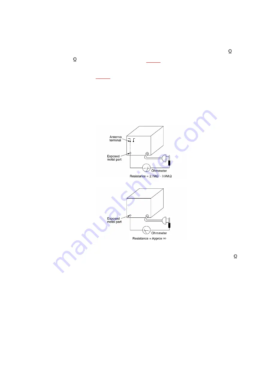
Equipment with antenna terminals should read between 2.7M
and3.9M to all exposed parts*. (
Fig.1
) / Equipment without
antenna terminals should read approximately infinity to all
exposed parts. (
Fig.2
) / *Note: Some exposed parts may be
isolated from the chassis by design. These will read infinity.
4. If the measurement is outside the specified limits, there is a
possibility of a shock hazard. The equipment should be repaired
and rechecked before it is returned to the customer.
Fig.1
Fig.2
2. Before Repair and adjustment
Disconnect AC power, discharge Power Supply Capacitors C566-569 and C591 through a 10 ,
5W resistor to ground. / DO NOT SHORT-CIRCUIT DIRECTLY (with a screwdriver blade, for
instance), as this may destroy solid state devices. / Afterrepairs are completed, restore power
gradually using a variac, to avoid overcurrent. / Current consumption at AC120V, 60Hz in NO
SIGNAL mode should be less than 750mA.
3. Protection Circuitry
The protection circuitry may have operated if either of the following conditions are noticed:
- No sound is heard when the power is turned on.
- Sound stops during a performance.
The function of this circuitry is to prevent circuitry damage if, for example, the positive and
negative speaker connection wires are “shorted”, or if speaker systems with an impedance less
than the indicated rated impedance ofthe amplifier are used. / If this occurs, follow the procedure
5
Summary of Contents for SA-DK3
Page 9: ...8 Location of Controls for Remote Control Transmitter 9 ...
Page 11: ...9 1 Checking for the main P C B and DVD module 1 P C B 11 ...
Page 12: ... Check the main P C B and DVD module 1 P C B A side as shown below 12 ...
Page 14: ...14 ...
Page 16: ...16 ...
Page 19: ... Check the DVD module 2 P C B as shown below 19 ...
Page 21: ...21 ...
Page 23: ...23 ...
Page 24: ...24 ...
Page 25: ...25 ...
Page 27: ...27 ...
Page 28: ...28 ...
Page 30: ...30 ...
Page 31: ...31 ...
Page 32: ...32 ...
Page 33: ...33 ...
Page 34: ...34 ...
Page 35: ...35 ...
Page 36: ...36 ...
Page 37: ...37 ...
Page 38: ...38 ...
Page 39: ...39 ...
Page 40: ...40 ...
Page 41: ...41 ...
Page 44: ... Follow the Step 1 Step 14 of item 9 4 44 ...
Page 45: ...45 ...
Page 46: ...46 ...
Page 48: ... Follow the Step 1 Step 4 of item 9 3 3 48 ...
Page 49: ...49 ...
Page 51: ...51 ...
Page 52: ...52 ...
Page 72: ...Q504 KTC3199GRTA TRANSISTOR 1 M 72 ...
Page 85: ...R213 ERJ6GEYJ682V 6 8K 1 10W 1 M 85 ...
Page 106: ...C631 ECBT1H104KB5 0 1 50V 1 M 106 ...
Page 109: ...C821 ECUV1H222KBN 2200P 50V 1 M 109 ...
Page 118: ...118 ...
Page 119: ...19 Mechanism Parts Location 119 ...
Page 120: ...120 ...
Page 121: ...20 CD Mechanism Parts Location 121 ...
Page 122: ...122 ...
Page 123: ...21 Packaging 123 ...
Page 124: ...Printed in Japan M000500000MT 124 ...


