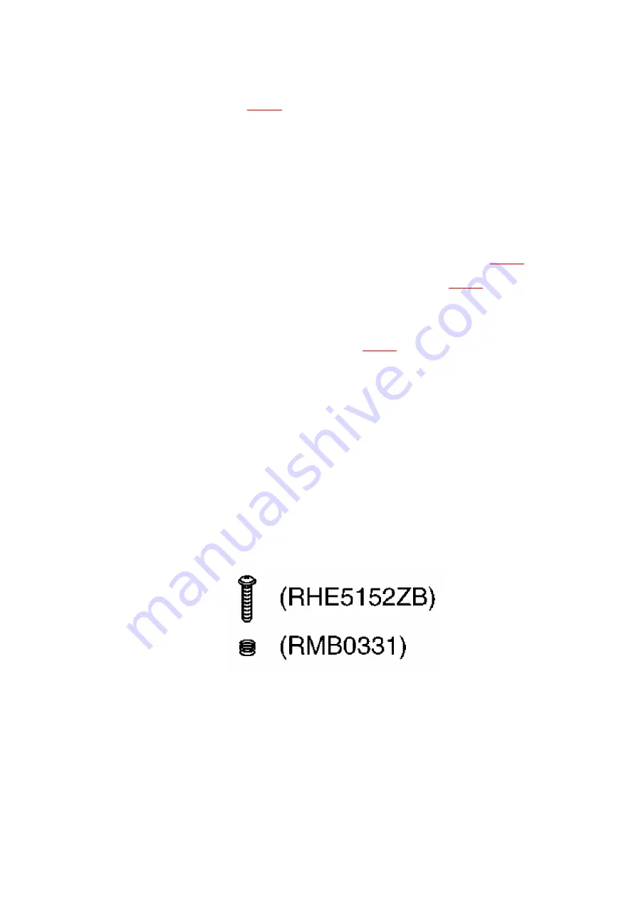
azimuth. (Shown in
Fig.1
). / Even if you wish to readjust the head
azimuthwithout replacing the screws and springs, a fine
adjustment cannot be done because of the screw-locking bond
adhered to the azimuth screw and spring.
- Please remove the screw-locking bond left on the head base when
replacing the azimuth screw.
- If you wish to readjust the head azimuth, be sure to adjust with
adhering the cassette tape closely to the mechanism by pushing
the center of cassette tape with your finger. (shown in
Fig.2
)
1. Connect the measuring instrument as shown in
Fig.3
.
2. Playback the azimuth adjustment portion (8kHz, -20dB) of test tape
(QZZCFM). Adjust the azimuth adjusting screw until the outputs of
the L/R-ch are maximized. (Refer to
Fig.4
) / Make surethat the
difference in the peak level between the left and right channels
does not exceed 0.5dB.
3. Perform the same adjustment in reverse playback mode. /
Checking of the level difference forward and reverse directions
4. Playback the playback gain adjustment portion (315Hz, 0dB) of
test tape (QZZCFM). Check if level difference between forward and
reverse direction is within 1.5dB.
5. After the adjustment, apply screwlock to the azimuth adjusting
screw.
Fig.1
Fig.2
56
Summary of Contents for SA-DK3
Page 9: ...8 Location of Controls for Remote Control Transmitter 9 ...
Page 11: ...9 1 Checking for the main P C B and DVD module 1 P C B 11 ...
Page 12: ... Check the main P C B and DVD module 1 P C B A side as shown below 12 ...
Page 14: ...14 ...
Page 16: ...16 ...
Page 19: ... Check the DVD module 2 P C B as shown below 19 ...
Page 21: ...21 ...
Page 23: ...23 ...
Page 24: ...24 ...
Page 25: ...25 ...
Page 27: ...27 ...
Page 28: ...28 ...
Page 30: ...30 ...
Page 31: ...31 ...
Page 32: ...32 ...
Page 33: ...33 ...
Page 34: ...34 ...
Page 35: ...35 ...
Page 36: ...36 ...
Page 37: ...37 ...
Page 38: ...38 ...
Page 39: ...39 ...
Page 40: ...40 ...
Page 41: ...41 ...
Page 44: ... Follow the Step 1 Step 14 of item 9 4 44 ...
Page 45: ...45 ...
Page 46: ...46 ...
Page 48: ... Follow the Step 1 Step 4 of item 9 3 3 48 ...
Page 49: ...49 ...
Page 51: ...51 ...
Page 52: ...52 ...
Page 72: ...Q504 KTC3199GRTA TRANSISTOR 1 M 72 ...
Page 85: ...R213 ERJ6GEYJ682V 6 8K 1 10W 1 M 85 ...
Page 106: ...C631 ECBT1H104KB5 0 1 50V 1 M 106 ...
Page 109: ...C821 ECUV1H222KBN 2200P 50V 1 M 109 ...
Page 118: ...118 ...
Page 119: ...19 Mechanism Parts Location 119 ...
Page 120: ...120 ...
Page 121: ...20 CD Mechanism Parts Location 121 ...
Page 122: ...122 ...
Page 123: ...21 Packaging 123 ...
Page 124: ...Printed in Japan M000500000MT 124 ...


