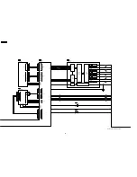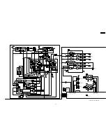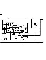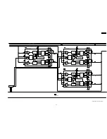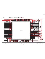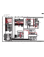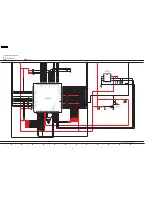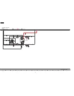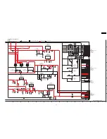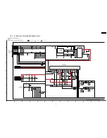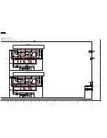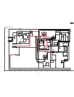
18 Schematic Diagram
·
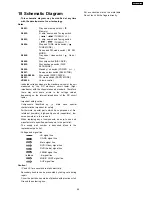
This schematic diagram may be modified at any time
with the development of new technology.
Notes:
S6801:
Play and memory switch (
Memory).
S6802:
R. skip, search and Tuning switch
(
/
/ TUNING
).
S6803:
F. skip, search and Tuning switch
(
/
/ TUNING
).
S6804:
Stop and TUNE mode switch (
TUNE MODE). /
Pause and FM mode switch (
FM
MODE).
S6808:
Tray open / close switch (
Open /
Close).
S6806:
Disc skip switch (DISC SKIP).
S6805:
Disc exchange switch (DISC
EXCHANGE).
S6900:
Standby / on switch (POWER
).
S6907:
Source select switch (SELECTOR).
S6902-S6906:
Disc switch (DISC1-DISC5).
S6901:
CD mode switch [PARTY MODE].
VR6800:
Volume control.
·
Indicated voltage values are the standard values for the unit
measured by the DC electronic circuit tester (high-
impedance) with the chassis taken as standard. Therefore,
there may exist some errors in the voltage values,
depending on the internal impedance of the DC circuit
tester.
·
Important safety notice:
Components
identified
by
mark
have
special
characteristics important for safety.
Furthermore, special parts which have purposes of fire-
retardant (resistors), high-quality sound (capacitors), low-
noise (resistors), etc. are used.
When replacing any of components, be sure to use only
manufacturer´s specified parts shown in the parts list.
·
The supply part number is described alone in the
replacement parts list.
·
Voltage and signal line
: +B signal line
: CD-DA signal line
: Main signal line
: DVD (Video) signal line
: DVD (Audio) signal line
: FM/AM signal line
: -B signal line
: MUSIC PORT signal line
: AUX signal line
Caution!
IC and LSI are sensitive to static electricity.
Secondary trouble can be prevented by taking care during
repair.
Cover the parts boxes made of plastics with aluminum foil.
Ground the soldering iron.
Put a conductive mat on the work table.
Do not touch ith the fingers directly.
69
SA-HT640WPL
Summary of Contents for SA-HT640WPL
Page 4: ...23 2 Packaging 109 24 Replacement Parts List 110 24 1 Component Parts List 111 4 SA HT640WPL ...
Page 10: ...10 SA HT640WPL ...
Page 16: ...16 SA HT640WPL ...
Page 19: ...8 2 Detail Block Diagram Receiver module 19 SA HT640WPL ...
Page 31: ...31 SA HT640WPL ...
Page 37: ...10 1 Disassembly Flow Chart 37 SA HT640WPL ...
Page 38: ...10 2 Main Components and P C B Locations 38 SA HT640WPL ...
Page 46: ...Step 3 Push tray assembly to the direction of arrow shown 46 SA HT640WPL ...
Page 53: ...14 2 Main P C B 53 SA HT640WPL ...
Page 60: ...SA HT640WPL 60 ...
Page 68: ...SA HT640WPL 68 ...
Page 70: ...70 SA HT640WPL ...
Page 80: ...SA HT640WPL 80 ...
Page 86: ...SA HT640WPL 86 ...
Page 88: ...SA HT640WPL 88 ...
Page 97: ...97 SA HT640WPL ...
Page 104: ...21 3 4 2 Receiver Module P C B 104 SA HT640WPL ...
Page 106: ...23 Explode Views 23 1 Cabinet Parts Location 106 SA HT640WPL ...
Page 107: ...107 SA HT640WPL ...
Page 108: ...108 SA HT640WPL ...
Page 109: ...23 2 Packaging 109 SA HT640WPL ...


