19
7 Troubleshooting Guide
7.1.
Audio
Audio confirmation
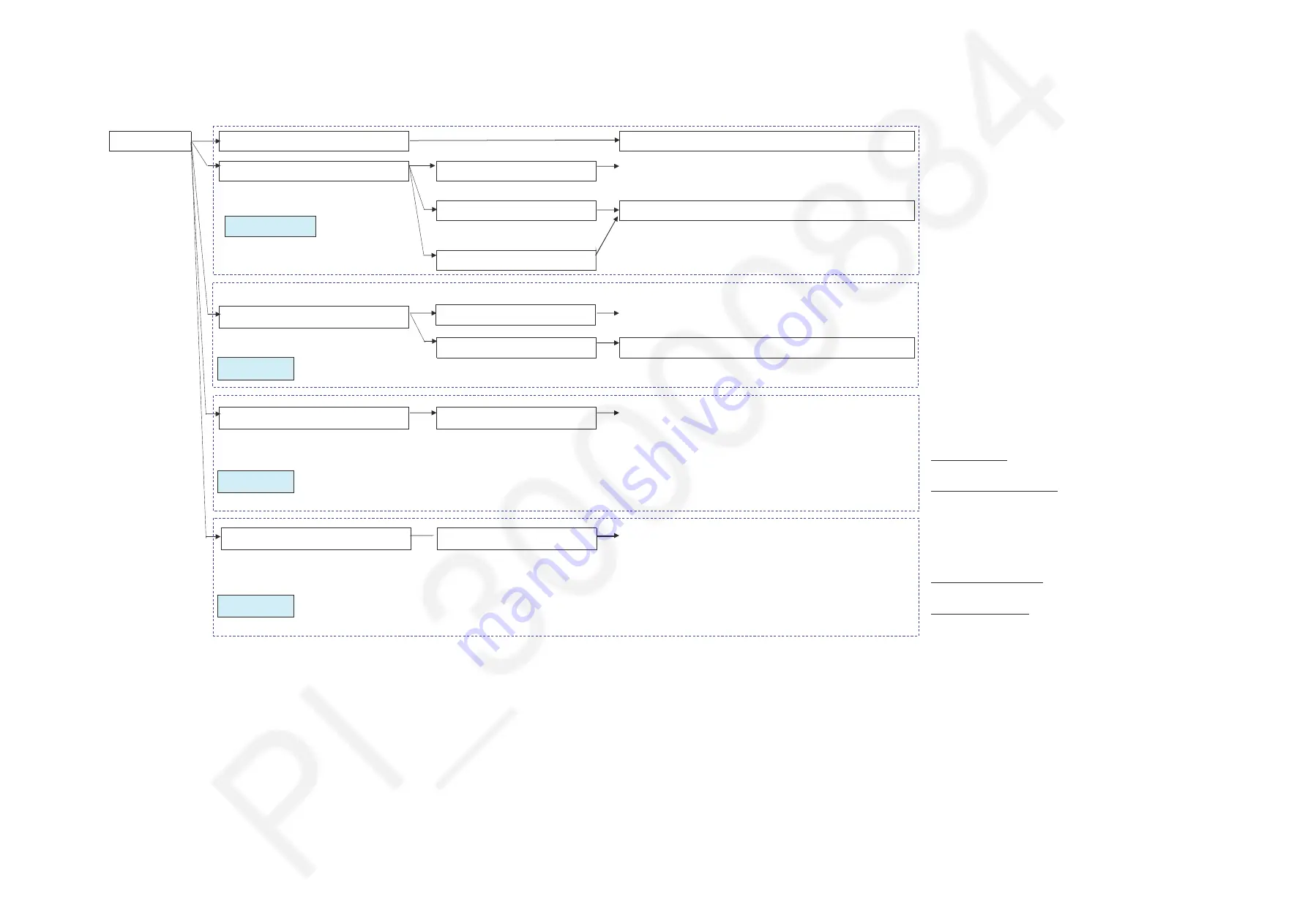
Sound skip from front speaker (Bluetooth input)
Check the radio wave interference of other wireless equipment (cordless phone,
microwave oven, WiFi, other BT devices).
No sound from front speaker (Bluetooth input)
VFD display BLUETOOTH READY
(PAIRING OK)
Check the connection to front speaker
VFD does not display your Device name
(PAIRING FAILED)
Check BT module connection at Main P.C.B.
Unable to view MAX4000 in list of BT
devices in external BT device
Check the connection to front speaker
VFD display NO USB
Check the Connection USB P.C.B. to Main P.C.B.
No Outout From AUX1/2
No Output from AUX 1/2
Check the connection to front speaker
Check Connection between Mic to Main
* Check the connection to front speaker
* Check Connection Mic P.C.B to Main P.C.B.
Bluetooth (BT)
Bluetooth (BT)
Module
Module
USB
USB
AUX1/2
AUX1/2
Mic
Mic
No Outout From USB
VFD display Track
No Outout From Mic
No Output From Mic
Check Main board (Micon/DSP & Digital Amplifier Circuit)
Check Mic P.C.B connector CN1401 (AUX2)
Check Main P.C.B connector CN2507
At Main Check IC6100
VCC Pin 16 = +12V
Selector Pin 10 = +12V (AUX1 ) , 0V (AUX2)
At Main Board Check Tuner IC (IC52)
VDD Pin 10,11 = +3.3V
Check Panel board connector CN1401
Check Mainl board connector CN2507
At Panel Check IC1400 & IC1401
VCC Pin 9 = +12V
At Main Board Check IC4802
VDD Pin 4 = +3.3V
VCC Pin 3 = +5.6V
Place other wireless equipment more than 2 meters away from main unit
Check Main P.C.B (Micon/DSP & Digital Amplifier Circuit)
Check Button Left P.C.B for connector P1500 & P1504
Check Main P.C.B connection CN2506
Check Q2117 Col5V
Check connection Bluetooth data UART_TX & UART_RX (IC 1001 Pin 101&102)
If all above are OK, BT module failure--> Change New BT Module
Check Main P.C.B (Micon/DSP & Digital Amplifier Circuit)
Check USB P.C.B connector CN9001 & CN9002
Check Main P.C.B connector CN2508 & CN2509
Check IC2101 Pin 10 fter L2102 = +5.6V
Check connection USB data D+/D- (IC 1001 Pin 97 & 98)
Summary of Contents for SA-MAX4000
Page 11: ...11 5 Location of Controls and Components 5 1 Remote Control Key Button Operation ...
Page 12: ...12 5 2 Main Unit Key Button Operation ...
Page 18: ...18 ...
Page 25: ...25 8 3 Main Components and P C B Locations ...
Page 38: ...38 ...
Page 48: ...48 ...
Page 50: ...50 ...
Page 74: ...74 ...
Page 80: ...80 ...
Page 97: ...97 MMH1504 ...


