8.4.
Self-Diagnostic Mode
8.5.
Self-Diagnostic Error Code Table
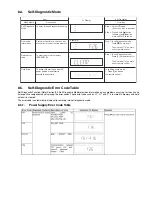
Self-Diagnostic Function (Refer Section 8.4. Self-Diagnostic Mode) provides information on any problems occurring for the unit and
its respective components by displaying the error codes. These error code such as U**, H** and F** are stored in memory and held
unless it is cleared.
The error code is automatically display after entering into self-diagnostic mode.
8.5.1.
Power Supply Error Code Table
FL Display
Key Operation
Front Key
Item
Description
Mode Name
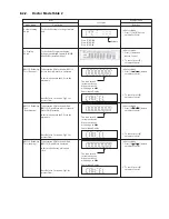
To enter into self diagnostic checking
System will perform a check on any
unusual/error code from the memory
To clear the stored in memory
(EEPROM IC)
Self Diagnostic
Mode
Error code
information
Delete error
code
Step 1: Select CD mode
(Ensure no disc is inserted).
Step 2: Press & hold [ ] button
follow by [
] on
main unit for 2 seconds.
Step 1: In self diagnostic mode,
Press [ ] on main unit.
To exit, press [
^
/I] on main
unit or remote control.
Step 1: In self diagnostic mode,
Press [0] on remote control.
To exit, press [
^
/I] on main
unit or remote control.
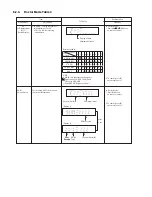
Example:
/
Cold Start
To active cold start upon next AC
power up when reset start is
execute the next time.
In
self diagnostic mode
:
1. Press [3] button on
the remote control.
Summary of Contents for SA-MAX500LMK
Page 14: ...5 General Introduction 5 1 Media Information ...
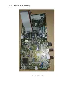
Page 26: ...9 1 2 Main P C B Front Side Fig 2 Main P C B Front Side Regulator Circuit IC2014 ...
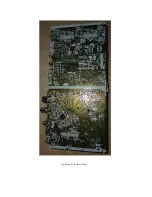
Page 27: ...Fig 3 Main P C B Back Side ...
Page 30: ...9 3 D Amp IC Operation Control MAX500 ...
Page 34: ......
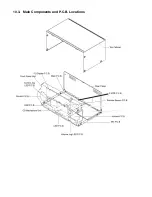
Page 36: ...10 3 Main Components and P C B Locations SMPS P C B ...
Page 84: ...14 3 FL Display Circuit MAX500 ...
Page 85: ...14 4 Volume Circuit MAX500 ...
Page 86: ...MAX500 14 5 Control USB Circuit ...
Page 87: ...14 7 Remote Sensor MAX500 ...
Page 88: ...MAX500 ...
Page 89: ... Jog Board MAX500 ...
Page 90: ...Internal Fan MAX500 ...
Page 124: ...17 1 3 Mechanical Replacement Part List ...


