9 Troubleshooting Guide
9.1.
Part Location
9.1.1.
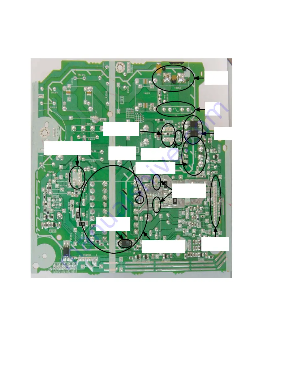
SMPS P.C.B.
Fig. 1 SMPS P.C.B.
Thermistor :
TH5861
Photocoupler :
PC5720
AC Inlet :
P5701
Fuse :
F1
Photocoupler :
PC5702, PC5799
Switching Regulator IC :
IC5701
SMPS Control IC :
IC5799
Main Tr ansformer :
T5701
Rectifier Diode :
D5801, D5802
Connector :
CN5802
Sub Transformer :
T5751
Sub Transformer :
D5798
Summary of Contents for SA-MAX500LMK
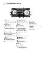
Page 14: ...5 General Introduction 5 1 Media Information ...
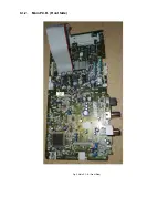
Page 26: ...9 1 2 Main P C B Front Side Fig 2 Main P C B Front Side Regulator Circuit IC2014 ...
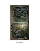
Page 27: ...Fig 3 Main P C B Back Side ...
Page 30: ...9 3 D Amp IC Operation Control MAX500 ...
Page 34: ......
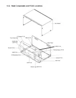
Page 36: ...10 3 Main Components and P C B Locations SMPS P C B ...
Page 84: ...14 3 FL Display Circuit MAX500 ...
Page 85: ...14 4 Volume Circuit MAX500 ...
Page 86: ...MAX500 14 5 Control USB Circuit ...
Page 87: ...14 7 Remote Sensor MAX500 ...
Page 88: ...MAX500 ...
Page 89: ... Jog Board MAX500 ...
Page 90: ...Internal Fan MAX500 ...
Page 124: ...17 1 3 Mechanical Replacement Part List ...


