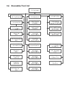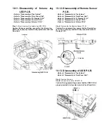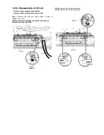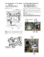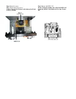
10.2. Disassembly Flow Chart
10.4. Top Cabinet
10.5. Front Panel Unit
10.14. Mic P.C.B.
10.6. FL Display
P.C.B.
10.12. Remote Sensor
P.C.B.
10.19. USB P.C.B.
Music Port
P.C.B.
Bottom Bar
LED P.C.B.
10.19. Main P.C.B.
10.21. SMPS P.C.B.
10.20. D-Amp P.C.B.
Voltage Regulator
IC (IC2010)
10.22. Switching
Regulator IC (IC5701)
10.23. Rectifier Diode
(D5702, D5801)
10.24. Rectifier Diode
(D5802, D5803)
10.17. CD Mechanism
Unit (BRS11C)
10.25. CD Interface
P.C.B.
CD Servo P.C.B.
Rear Panel
Voltage Regulator
IC (IC2011)
Amp IC (IC5800)
Audio Digital
Audio Digital
Audio Digital
Audio Digital
Amp IC (IC5400)
Amp IC (IC5000)
Amp IC (IC5200)
Amp IC (IC5300)
Audio Digital
Audio Digital
Amp IC (IC5700)
Memory LED
P.C.B.
10.10. Volume
LED P.C.B.
10.8. Control Jog
P.C.B.
Summary of Contents for SA-MAX500LMK
Page 14: ...5 General Introduction 5 1 Media Information ...
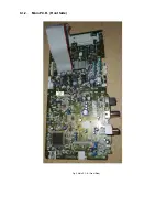
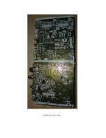
Page 26: ...9 1 2 Main P C B Front Side Fig 2 Main P C B Front Side Regulator Circuit IC2014 ...
Page 27: ...Fig 3 Main P C B Back Side ...
Page 30: ...9 3 D Amp IC Operation Control MAX500 ...
Page 34: ......
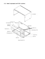
Page 36: ...10 3 Main Components and P C B Locations SMPS P C B ...
Page 84: ...14 3 FL Display Circuit MAX500 ...
Page 85: ...14 4 Volume Circuit MAX500 ...
Page 86: ...MAX500 14 5 Control USB Circuit ...
Page 87: ...14 7 Remote Sensor MAX500 ...
Page 88: ...MAX500 ...
Page 89: ... Jog Board MAX500 ...
Page 90: ...Internal Fan MAX500 ...
Page 124: ...17 1 3 Mechanical Replacement Part List ...

