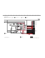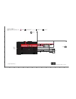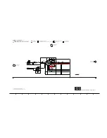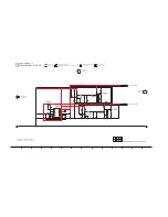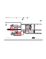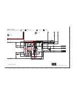
14 Schematic Diagram
16.1. Schematic Diagram Notes
This schematic diagram may be modified at any time
with the development of new technology.
Notes:
Important safety notice:
Components identified by
mark have special characteris-
tics important for safety.
Furthermore, special parts which have purposes of fire-retar-
dant (resistors), high quality sound (capacitors), low-noise
(resistors), etc are used.
When replacing any of components, be sure to use only
manufacturer’s specified parts shown in the parts list.
In case of AC rated voltage Capacitors, the part no. and val-
ues will be indicated in the Schematic Diagram.
AC rated voltage capacitors:
C5700, C5701, C5704, C5705, C5708
Resistor
Unit of resistance is OHM [
Ω
] (K=1,000, M=1,000,000).
Capacitor
Unit of capacitance is
μ
F, unless otherwise noted. F=Farads,
pF=pico-Farad.
Coil
Unit of inductance is H, unless otherwise noted.
*
REF IS FOR INDICATION ONLY.
Voltage and signal line
S6000:
Radio/EXT-IN switch.
S6001:
Stop (
) switch.
S6002:
Power (
) switch.
S6003:
Memory switch.
S6004:
Play/Pause (
/
) switch.
S6005:
CD switch.
S6006:
USB switch.
S6007:
D.BASS switch.
S6008:
Latin Preset EQ switch.
S6009:
Forward (
/
) switch.
S6010:
Rewind (
/
) switch.
S6011:
Super Woofer switch.
S6012:
Memory Rec/Pause switch.
S6013:
USB Rec/Pause switch.
S6014:
Album/Track switch.
S6015:
Open/Close switch (
).
S6016:
Manual EQ switch.
S7201:
Reset switch.
VR6000:
Volume Jog.
VR6001:
Album/Track Jog.
VR6500:
Mic Jog.
: +B signal line
: -B signal line
: CD Audio input signal line
: AUX/Tuner/Music Port/Mic Audio input signal line
: Audio output signal line
: USB signal line
: AM signal line
: FM signal line
Playlist 2 switch.
Playlist 3 switch.
Playlist 4 switch.
Playlist 1 switch.
Playlist 5 switch.
Playlist 6 switch.
Summary of Contents for SA-MAX500LMK
Page 14: ...5 General Introduction 5 1 Media Information ...
Page 26: ...9 1 2 Main P C B Front Side Fig 2 Main P C B Front Side Regulator Circuit IC2014 ...
Page 27: ...Fig 3 Main P C B Back Side ...
Page 30: ...9 3 D Amp IC Operation Control MAX500 ...
Page 34: ......
Page 36: ...10 3 Main Components and P C B Locations SMPS P C B ...
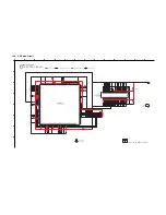
Page 84: ...14 3 FL Display Circuit MAX500 ...
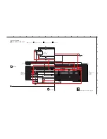
Page 85: ...14 4 Volume Circuit MAX500 ...
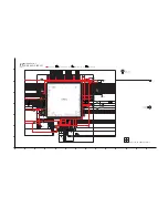
Page 86: ...MAX500 14 5 Control USB Circuit ...
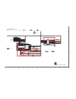
Page 87: ...14 7 Remote Sensor MAX500 ...
Page 88: ...MAX500 ...
Page 89: ... Jog Board MAX500 ...
Page 90: ...Internal Fan MAX500 ...
Page 124: ...17 1 3 Mechanical Replacement Part List ...

