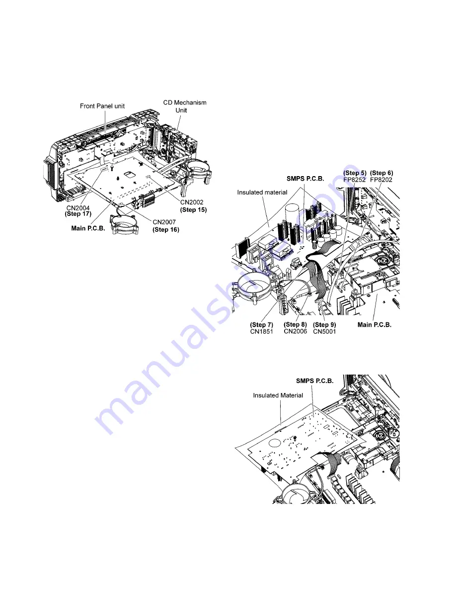
Step 14 Attach 30P FFC at the connector (CN2004) on Main
P.C.B..
Step 15 Attach 10P FFC at the connector (CN2002) on Main
P.C.B..
Step 16 Attach 2P Wire at the connector (CN2007) on Main
P.C.B..
Step 17 Side A Main P.C.B. can be checked as diagram shown.
10.4. Checking of SMPS P.C.B.
Step 1 Remove Top Cabinet.
Step 2 Remove Rear Panel.
Step 3 Remove CD Mechanism.
Step 4 Remove SMPS P.C.B..
Step 5 Attach 10P FFC at the connector (FP8252) on Main
P.C.B..
Step 6 Attach 24P FFC at the connector (FP8202) on Main
P.C.B..
Step 7 Attach 11P Cable at the connector (CN1851) on SMPS
P.C.B..
Step 8 Attach 2P Wire at the connector (CN2006) on Main
P.C.B..
Step 9 Attach 12P Wire at the connector (CN5001) on Main
P.C.B..
Step 10 Upset the SMPS P.C.B..
Step 11 The SMPS P.C.B. can be checked as diagram shown.
Summary of Contents for SA-MAX750LMK
Page 13: ...5 General Introduction 5 1 Media Information ...
Page 14: ...6 Location of Controls and Components 6 1 Remote Control Key Button Operation ...
Page 15: ...6 2 Main Unit Key Button Operation ...
Page 17: ...7 1 1 Service Mode Table ...
Page 24: ...8 Troubleshooting Guide Contents for this section is not available at time of issue ...
Page 27: ...9 3 Main Components and P C B Locations ...
Page 83: ...PSG ...


