background image

47

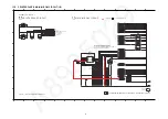
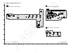
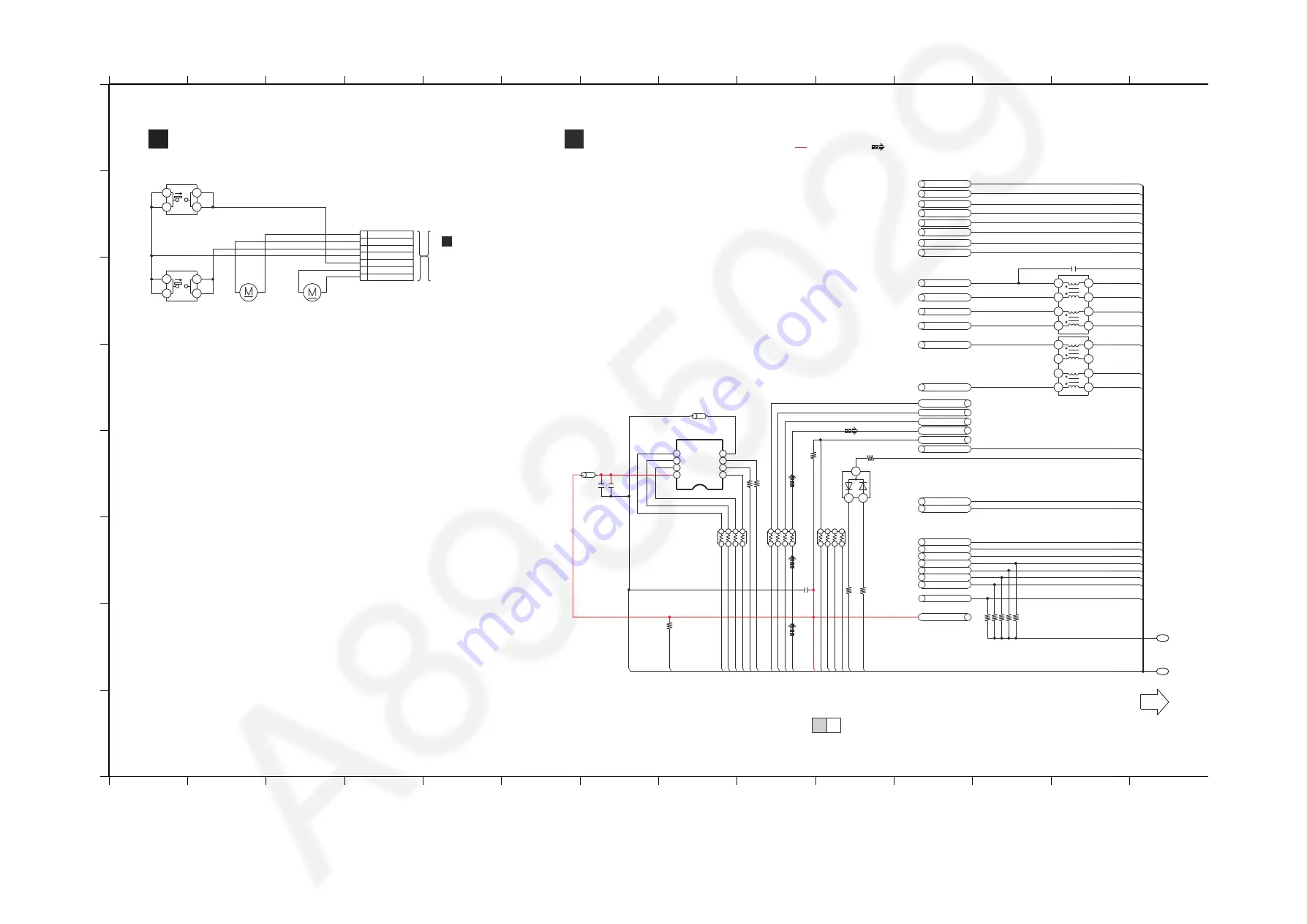
13.2. CD INTERFACE & MAIN (MICON) CIRCUIT (1/2)

A

1

2

3

4

5

6

7

8

9

10

11

1

2

13

14

1

2

3

4

5

6

7

8

9

10

11

1

2

13

14

C

D

B

E

G

H

F

A

 CD INTERF

A

CE CIRCUIT

B

 M

A

IN (MICON) CIRCUIT

S

CHEM

A

TIC DI

A

GR

A

M - 1


SA

-PM

2

50EB/EC/EE/EF/EG CD INTERF

A

CE / M

A

IN (MICON)

 CIRCUIT

2

/

2

1/

2

TO M

A

IN (MICON)

CIRCUIT (

2

/

2

)

1

P1

: +B 

S

IGN

A

L LINE

NOTE: “ * ” REF I

S

 FOR INDIC

A

TION ONLY

B

TO
M

A

IN (CD MOTOR DRI

V

ER)

CIRCUIT (

CN5001

)

IN 

S

CHEM

A

TIC 

DI

A

GR

A

M - 5

S

U: M

A

IN (

S

UPPLY): 

S

CHEM

A

TIC DI

A

GR

A

M - 3

D

A

: M

A

IN (D

A

MP): 

S

CHEM

A

TIC DI

A

GR

A

M - 4

CD: M

A

IN (CD MOTOR DRI

V

ER): 

S

CHEM

A

TIC DI

A

GR

A

M - 5

U

S

: M

A

IN (U

S

B): 

S

CHEM

A

TIC DI

A

GR

A

M - 

6

: CD 

A

UDIO INPUT 

S

IGN

A

L LINE

1

7

0

R8048

D

S

P_

S

D

A

D

S

P_

S

D

A

D

S

P_MUTE

D

S

P_ERR

D

S

P_RE

S

ET

D

S

P_

S

CL

D

S

P_RE

S

ET

D

S

P_ERR

D

S

P_

S

CL

D

S

P_MUTE

LO

A

DING

S

MP

S

_ID

S

MP

S

_CUT

M_

V

DET

M_

V

DET

S

TBY_CTRL

S

MP

S

_ID

S

MP

S

_CUT

CD_

S

DO

CD_LRCK

CD_BCK

S

TBY_CTRL

PCONT3

DC_DET_PWR

INNER_

S

W

CD

CD

D

A

D

A

D

A

D

A

D

A

D

A

D

A

D

A

S

U

S

U

D

A

D

A

D

A

S

U

S

U

S

U

D

A

D

A

D

A

D

A

U

S

U

S

D

A

S

U

S

U

D

A

D

A

D

A

S

U

R80

2

4

100K

R80

2

8

100K

FL_C

S

FL_DO

100

R804

7

FL

PCONT

6

8

7

5

2

1

4

3

J0J

A

D000000

7

RX800

7

100P

C8054

6

8

7

5

2

1

4

3

RX8008

J0J

A

D000000

7

U

S

B_O

V

C

U

S

B_EN

BT_U

A

RT_RT

S

DC_DET_

A

MP

BT_PCONT

PW_

S

TBY3R3

V

LB8004

J0JYC0000

6

5

6

R8

2

08

10K

10

C803

2

0.1

C80

6

4

R8050

100K

8

6

5

7

4

2

1

3

RX8010

D1H81014

A

04

2

0.1

C8031

J0JHC0000118

LB8009

2

1

7

8

4

3

6

5

RFKWFPM

2

50EM

1

6

M FL

AS

H MEMORY

IC8003

8

6

5

7

4

2

1

3

D1H81014

A

04

2

RX8009

R805

72

2

0

R805

62

2

0

8

6

5

7

4

2

1

3

RX8011

D1H8

22

14

A

04

2

DIMMER

OPEN_

S

W

TU_

S

CL

R80

26

4.

7

K

R80

27

4.

7

K

R80

2

5

100K

TU_

S

D

A

TU_INT

100

R804

6

TU_R

S

T

INNER_

S

W

FL_C

S

FL_DO

CLK_FL

DIMMER

OPEN_

S

W

CLK_TU_

S

CL

TU_

S

D

A

TU_INT

TU_R

S

T

3

1

2

D8000

B0

A

DDH000009

LRCKI1

DGND

PCONT

DC_DET_

A

MP

U

S

B_EN

A

BLE

U

A

RT_RT

S

U

S

B_O

V

C

BT_PCONT

GPIO09

S

CL0

S

D

A

0

CLK

DI(DQ0)

WP#(DQ

2

)

VSS

V

CC

HOLD#(DQ3)

C

S

#

DO(DQ1)

CD I

2S

 BCK

DC_DET_PWR

PW_

S

TBY3R3

V

CD I

2S

 D

A

T

A

FL_CLK

FL_D

A

T0

DGND

S

TBY_CTRL

FL_D

A

T

2

PCONT3

FL_D

A

T3

FL_D

A

T1

FL_C

S

CD I

2S

 LRCK

TR

V

_CW

TR

V

_CCW

4

3

1

2

S72

00

OPEN

4

3

1

2

S72

01

RE

S

ET

+

M

7

30

2

*

4

5

1

3

2

7

6

CN

7

00

2

+

M

7

301*

TR

AV

ER

S

E MOTOR

S

PINDLE MOTOR

TR

V

-

TR

V

+

MOTORGND

RE

S

T_

S

W

S

PM-

S

PM+

OPEN_

S

W

Summary of Contents for SA-PM250EB

Page 1: ...rt Information 5 2 Warning 6 2 1 Prevention of Electrostatic Discharge ESD to Electrostatically Sensitive ES Devices 6 2 2 Precaution of Laser Diode 7 2 3 Service caution based on Legal restrictions 8 2 4 Handling Precaution for Traverse Unit 9 3 Service Navigation 11 3 1 Service Information 11 4 Specifications 12 5 Location of Controls and Components 13 5 1 Main Unit Remote Control Key Button Ope...

Page 2: ... P C B 36 10 2 Checking of Panel P C B 36 10 3 Checking of CD Interface P C B 37 10 4 Checking of Main P C B Side A 38 10 5 Checking of Main P C B Side B 39 11 Block Diagram 41 11 1 SYSTEM CONTROL AUDIO BLOCK DIAGRAM 41 11 2 POWER SUPPLY BLOCK DIAGRAM 42 12 Wiring Connection Diagram 43 13 Schematic Diagram 45 13 1 Schematic Diagram Notes 45 13 2 CD INTERFACE MAIN MICON CIRCUIT 1 2 47 13 3 MAIN MIC...

Page 3: ...ock hazards 1 1 1 Leakage Current Cold Check 1 Unplug the AC cord and connect a jumper between the two prongs on the plug 2 measure the resistance value with an ohmmeter between the jumpered AC plug and each exposed metallic cabinet part on the equipment such as screwheads connectors control shafts etc When the exposed metallic part has a return path to the chassis the reading should be between 1M...

Page 4: ...on circuitry may have operated if either of the following conditions are noticed No sound is heard when the power is turned on Sound stops during a performance The function of this circuitry is to prevent circuitry damage if for example the positive and negative speaker connection wires are shorted or if speaker systems with an impedance less than the indicated rated impedance of the amplifier are...

Page 5: ...F EG 23 RGN3453A K NAME PLATE EE 29 RMV0442 SMPS COVER SHEET 301 RAE1028Z V TRAVERSE UNIT A2 K2CQ2YY00119 AC CORD EC EE EF EG A2 K2CT2YY00097 AC CORD EB A3 RQT9926 B O I BOOK En EB EC A3 RQT9927 D O I BOOK Fge Fr It Du EG A3 RQT9928 H O I BOOK Fr EF A3 RQT9929 E O I BOOK Sw Da Sp Cz Po Fi EC A3 RQT9930 1R O I BOOK Ru Ur EE PCB5 REP5070AA SMPS P C B RTL Z1752 D4EAY511A182 VARISTOR L1702 G0B922G0000...

Page 6: ...solder or unsolder ES devices 4 Use only an anti static solder removal device Some solder removal devices not classified as anti static ESD protected can generate electrical charge sufficient to damage ES devices 5 Do not use freon propelled chemicals These can generate electrical charges sufficient to damage ES devices 6 Do not remove a replacement ES device from its protective package until imme...

Page 7: ...r a long time ACHTUNG Dieses Produkt enthält eine Laserdiode Im eingeschalteten Zustand wird unsichtbare Laserstrahlung von der Lasereinheitadg estrahit Wellenlänge 790nm CD Maximale Strahlungsleistung der Lasereinheit 100 μW VDE Die Strahlung an der Lasereinheit ist ungefährlich wenn folgende Punkte beachtet werden 1 Die Lasereinheit nicht zerlegen da die Strahlung an der freigelegten Laserdiode ...

Page 8: ...is used Definition The letter of PbF is printed on the PCB using the lead free solder To put lead free solder it should be well molten and mixed with the original lead free solder Remove the remaining lead free solder on the PCB cleanly for soldering of the new IC Since the melting point of the lead free solder is higher than that of the normal lead solder it takes the longer time to melt the lead...

Page 9: ... Special care must be taken avoid caution to electrostatic discharge damage when servicing the laser diode 1 Do not give a considerable shock to the optical pickup unit as it has an extremely high precise structure 2 To prevent the laser diode from the electrostatic discharge damage the flexible cable of the optical pickup unit removed should be short circuited with a short pin or a clip 3 The fle...

Page 10: ...ctricity in the working environment Proceed servicing works under the working environment where grounding works is completed 2 4 2 1 Worktable grounding 1 Put a conductive material sheet or iron sheet on the area where the optical pickup is placed and ground the sheet 2 4 2 2 Human body grounding 1 Use the anti static wrist strap to discharge the static electricity form your body ...

Page 11: ...is changed or modified this information will be followed by supplement service manual to be filed with original service manual 3 1 1 Firmware update Software Update through USB Steps 1 Power On Set 2 Go to USB selector 3 Plug In USB containing FW_IMAGE BIN FWUPDATE disc image file or PM250 FRM file 4 Display will show READING blink UPD 0 to 100 5 After Software Update complete display will be show...

Page 12: ...n Speaker unit s Full range 10 cm cone type x 1 per channel Impedance 6 Ω Dimensions W x H x D 139 mm x 224 mm x 136 mm Mass 1 3 kg Q General Power supply AC 220 to 240 V 50 Hz Power consumption 14 W Dimensions W x H x D 184 mm x 123 mm x 228 mm Mass 1 1 kg Operating temperature range 0 C to 40 C Operating humidity range 35 to 80 RH no condensation Power consumption in standby mode With BLUETOOTH ...

Page 13: ...13 5 Location of Controls and Components 5 1 Main Unit Remote Control Key Button Operations ...

Page 14: ...IRING on main unit for 2 second To exit press the TA on the main unit or using the remote control Unplug the AC cord Step 1 In self diagnostic mode Press STOP on main unit To exit press the TA on the main unit or using the remote control Unplug the AC cord Step 1 In self diagnosis mode press and hold OK on remote control for more than 5 second To exit press the TA on the main unit or using the rem...

Page 15: ...If cannot detect CD INNER SW need to memory error log F15 F26 LSI Communication Press on main unit for next error Communication between CD servo LSI and micro p abnormal include iPod USB of error Automatic FL Display Remarks F61 Press on main unit for next error Press on main unit for next error Error Code Diagnostic Contents Description of error DAMP output abnormal PDET2 DC_DET_AMP L NG PDET2 DC...

Page 16: ...ersion display To enter into Doctor Mode for checking of various items and displaying EEPROM check sum and Opecon firmware version Note The Opecon firmware version as shown is an example It will be revised when there is updates FL Display sequence Display 1 2 FL Display Test To check the FL segments display All segments will light up In Doctor Mode Press follow by 2 then 1 button on the remote con...

Page 17: ...t completed by 10s or the traverse is out of focus for more than 2s To exit Doctor Mode press TA button on main unit or on the remote control of HC35 Unplug the AC cord To exit Doctor Mode press TA button on main unit or on the remote control of HC35 Unplug the AC cord Cold Start The NO DISC display will appear after 2s In Doctor Mode Press 4 button on remote control To activate cold start upon ne...

Page 18: ...18 ...

Page 19: ... Main P C B Replace Main P C B PWM singnal output Pin25 30 31 36 from DSP D AMP IC400 is OK PWM singnal input Pin1 5 9 10 to DSP D AMP IC400 is OK Pin No Waveform Output Table 2 Table 2 Table 1 Pin No Voltage Value Table1 SMPS㧔P1700㧕 MAIN㧔CN1100 No power during power on of the unit Confirmation if AC Power from SMPS P C B to Main P C B Check AC Cord and AC Inlet replace them Is AC Power present at...

Page 20: ...20 ...

Page 21: ...s during repair Select items from the following indexes when disassembly or replacement are required Disassembly of Top Cabinet Assembly Disassembly of Bluetooth P C B Disassembly of Tuner P C B Disassembly of SMPS Unit Disassembly of SMPS P C B Disassembly of Front Panel Assembly Disassembly of Button P C B Volume P C B and Panel P C B Disassembly of CD Lid Disassembly of Main P C B Disassembly o...

Page 22: ...22 8 3 Type of screws 8 4 Main Parts Location Diagram ...

Page 23: ...23 8 5 Disassembly of Top Cabinet Assembly Step 1 Remove 4 screws Step 2 Remove 2 screws Step 3 Release catches Step 4 Lift up Top Cabinet Assembly ...

Page 24: ...ch 9P FFC at connector CN7001 on Bluetooth P C B Step 6 Remove Top Cabinet Assembly 8 6 Disassembly of Bluetooth P C B Refer to Disassembly of Top Cabinet Assembly Step 1 Remove 1 screw Step 2 Remove Bluetooth P C B ...

Page 25: ...crew Step 2 Detach 9P FFC at connector CN51 on Tuner P C B Step 3 Lift up and remove Tuner P C B 8 8 Disassembly of SMPS Unit Refer to Disassembly of Top Cabinet Assembly Step 1 Remove 1 screw Step 2 Remove 3 screws Step 3 Detach 10P cable at connector CN1100 on Main P C B Step 4 Remove SMPS Unit ...

Page 26: ...1 Release guides Step 2 Release guides Step 3 Remove SMPS Shield Caution During assembling ensure that the SMPS Shield is fully catched inside the SMPS Chassis Step 4 Remove SMPS P C B Caution During assembling ensure that the SMPS P C B is properly seated onto the locators ...

Page 27: ... Panel Assembly Refer to Disassembly of Top Cabinet Assembly Step 1 Detach 13P FFC at connector CN900 on Panel P C B Step 2 Slightly push inwards to release catches Step 3 Slightly push outwards Front Panel Assembly as arrow shown ...

Page 28: ...tom of Rear Cabinet Assembly Step 5 Remove Front Panel Assembly 8 11 Disassembly of Button P C B Volume P C B and Panel P C B Refer to Disassembly of Top Cabinet Assembly Refer to Disassembly of Front Panel Assembly Step 1 Remove 1 screw ...

Page 29: ...ly lift up and remove Button P C B Step 3 Release 3P cable from slots Step 4 Remove Volume Knob Step 5 Remove 3 screws Step 6 Release catches Step 7 Remove Volume P C B Step 8 Remove 2 screws Step 9 Remove Panel P C B ...

Page 30: ... Assembly Refer to Disassembly of Front Panel Assembly Step 1 Lift up and remove CD Lid Spring as arrow shown in order Caution Keep the CD Lid Spring in a safe place and place it back during assembling Step 2 Push the shaft R of the CD Lid inward Step 3 Remove CD Lid ...

Page 31: ...p 1 Remove 2 screws Step 2 Detach 10P cable at connector CN1100 on Main P C B Step 3 Detach 7P FFC at connector CN5001 on Main P C B Step 4 Detach 24P FFC at connector CN5002 on Main P C B Step 5 Detach 9P FFC at connector CN8002 on Main P C B Step 6 Lift up and remove Main P C B Step 7 Remove 2 screws Step 8 Remove Main P C B ...

Page 32: ...nit Refer to Disassembly of Front Panel Assembly Refer to Disassembly of Main P C B Step 1 Remove 2 screws Step 2 Remove CD Mechanism Unit 8 15 Disassembly of CD Interface P C B Refer to Disassembly of CD Mechanism Unit Step 1 Remove 2 screws Step 2 Desolder pins on CD Interface P C B Step 3 Remove CD Interface P C B ...

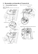
Page 33: ...f Traverse Unit 9 1 Disassembling Procedures Step 1 Release guide Step 2 Push traverse slide plate rib ensure both grooves are opened Step 3 Remove traverse unit as arrow shown Caution Avoid touching the surface of the traverse unit ...

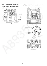
Page 34: ...4 9 2 Assembling Procedures Caution Removal of the short pin is necessary for replacement of new traverse unit Step 1 Release guide Step 2 Push the traverse slide plate rib ensure both grooves are opened ...

Page 35: ...Step 3 Insert Traverse Unit at approximately 45 as arrow shown Caution Ensure that the bosses fix exactly onto the guides Step 4 Release guide Step 5 Push traverse slide plate rib to lock the traverse unit ...

Page 36: ... Connect 10P wire at connector CN1100 on Main P C B Step 5 Check SMPS P C B according to the diagram shown 10 2 Checking of Panel P C B Step 1 Remove Top Cabinet Assembly Step 2 Remove Front Panel Assembly Step 3 Remove Button P C B Volume P C B and Panel P C B Step 4 Place Button P C B Volume P C B and Panel P C B on insulating material Step 5 Connect 13P extension cable REEX1203 from CN8001 on M...

Page 37: ...abinet Assembly Step 2 Remove SMPS Unit Step 3 Remove Front Panel Assembly Step 4 Remove Main P C B Step 5 Remove CD Mechanism Unit Step 6 Place Main P C B Front Panel Assembly and SMPS Unit on insulating material Step 7 Connect 10P wire at connector CN1100 on Main P C B Step 8 Connect 13P extension cable REEX1203 from CN8001 on Main P C B to CN900 on Panel P C B ...

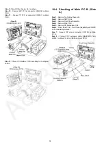
Page 38: ...n 10 4 Checking of Main P C B Side A Step 1 Remove Top Cabinet Assembly Step 2 Remove SMPS Unit Step 3 Remove Front Panel Assembly Step 4 Remove Main P C B Step 5 Remove CD Mechanism Unit Step 6 Place Main P C B Front Panel Assembly and SMPS Unit on insulating material Step 7 Connect 10P wire at connector CN1100 on Main P C B Step 8 Connect 13P extension cable REEX1203 from CN8001 on Main P C B to...

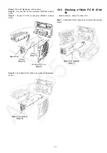
Page 39: ...tor CN5002 on Main P C B Step 11 Connect 7P FFC at connector CN5001 on Main P C B Step 12 Check Main P C B Side A according to the diagram shown 10 5 Checking of Main P C B Side B Refer to Step 1 Step 11 of item 10 3 Step 1 Check Main P C B Side B according to the diagram shown ...

Page 40: ...40 ...

Page 41: ... CN900 CN8001 VOL JOG BLUETOOTH PAIRING S903 TREBLE S902 BASS S901 PLAY PAUSE S909 FF S906 STOP S907 SELECTOR S904 REW S905 POWER S900 EJECT S910 X8002 127 XIN PLL 128 XOUT PLL X8001 M VDET PCONT SMPS CUT PCONT3 84 PCONT3 STBY CONTROL 93 M VDET 38 DC DET PWR DC DET PWR 77 STBY CTRL USB ENABLE 105 USB OVC 106 TRV CCW TRV CW SDOUT CLVOUT FDOUT TDOUT INNER SW OPEN SW LCD DRIVER C0HBA0000268 IC900 CD ...

Page 42: ...E REGULATOR C0DBGYY03909 3 VIN VOUT 2 D1103 D1100 Q1100 QR1101 SWITCH SWITCH MAIN P C B D1105 QR1102 PCONT 4 6 4 6 CN1100 P1700 16V 19V 1 1 CN1100 P1700 5 2V 5 2V 9 9 CN1100 P1700 PCONT3 PCONT3 PCONT 3 3 CN1100 P1700 PCONT PCONT 10 10 CN1100 P1700 BURST SW ECO CTR FEEDBACK CIRCUIT SMPS P C B F1700 Z1752 D1701 L1702 1 4 2 3 3 1 6 5 2 TRANSFORMER T1700 7 9 8 10 11 12 P1751 AC INLET D1703 D1708 IC170...

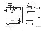
Page 43: ...8003 CN5001 CN5002 CN8002 CN400 ZJ902 ZJ903 CN900 ZJ901 ZJ904 P1751 P1700 220V 240V 50Hz AC IN A CD INTERFACE P C B B MAIN P C B C TUNER P C B G SMPS P C B F BUTTON P C B D PANEL P C B E VOLUME P C B 9P 10P 24P 7P 9P 13P 7P 9P 10P 3P 4P 13P 4P 3P TO OPTICAL PICKUP UNIT CD MECHANISM UNIT TO BLUETOOTH P C B SPEAKER USB ...

Page 44: ...44 ...

Page 45: ...Capacitors the part no and val ues will be indicated in the Schematic Diagram AC rated voltage capacitors C1702 C1710 C1725 C1727 C1728 Resistor Unit of resistance is OHM Ω K 1 000 M 1 000 000 Capacitor Unit of capacitance is μF unless otherwise noted F Farads pF pico Farad Coil Unit of inductance is H unless otherwise noted REF IS FOR INDICATION ONLY Voltage and signal line S900 POWER switch S901...

Page 46: ...46 ...

Page 47: ...A DA DA SU R8024 100K R8028 100K FL_CS FL_DO 100 R8047 FL PCONT 6 8 7 5 2 1 4 3 J0JAD0000007 RX8007 100P C8054 6 8 7 5 2 1 4 3 RX8008 J0JAD0000007 USB_OVC USB_EN BT_UART_RTS DC_DET_AMP BT_PCONT PW_STBY3R3V LB8004 J0JYC0000656 R8208 10K 10 C8032 0 1 C8064 R8050 100K 8 6 5 7 4 2 1 3 RX8010 D1H81014A042 0 1 C8031 J0JHC0000118 LB8009 2 1 7 8 4 3 6 5 RFKWFPM250EM 16M FLASH MEMORY IC8003 8 6 5 7 4 2 1 3...

Page 48: ...1 3 RX8001 D1H81014A042 C8059 100P C8005 C8002 100P C8004 1000P 100P C8003 100P DSP_MUTE DSP_ERR R8222 2 2K J0JYC0000656 LB8015 DSP_RESET J0JYC0000656 LB8013 J0JYC0000656 LB8014 C8001 0 1 C8000 0 1 3 1 2 4 5 IC8002 C0EBE0000338 RESET R8114 0 R8000 100 C8029 100P C8030 0 1 LB8010 J0JYC0000656 J0JYC0000656 LB8011 C8035 0 1 C8036 10 C8033 0 1 J0JYC0000656 LB8012 C8026 0 022 2 1 7 8 5 4 3 6 C3EBFY0000...

Page 49: ...27K R1105 R1100 100K LB1100 J0JYC0000656 C1137 1 C1187 100P J0JYC0000656 LB1101 2 2K R1150 R1129 150K 3 1 2 4 5 C0DBEYY00146 9V VOLTAGE REGULATOR IC1104 0 R1104 J0JGC0000063 LB1102 R1116 56K 1 C1130 1 C1131 DA PW_LCD9V DA VP_GND MI PW_STBY1R55V R1145 0 0 1 C1183 B0JCGD000016 D1103 3 1 2 B0ADDH000009 D1104 C1136 1 0 R1101 5 6 R1142 5 6 R1143 0 1 C1190 23 2K R1141 10K R1130 100P C1189 C1120 1 R1144 ...

Page 50: ...000231 DC DETECT B1ABCF000231 DC DETECT R430 100K R429 4 7K G1C100MA0426 L400 R431 22K J0JYC0000366 LB402 C433 10 R435 100K 100K R437 100K R436 C434 10 R434 100K J0JYC0000366 LB404 LB405 J0JYC0000366 J0JYC0000366 LB403 C436 1000P 1000P C435 C458 0 01 0 01 C457 C405 15P C407 2700P C406 0 027 C404 12P R413 1 5K R412 1M R414 1 5K R416 100K 2 3 1 4 H0J245500110 X400 C438 1000P 1000P C437 25V220 C410 D...

Page 51: ...0 1 C5011 10V10 C5019 1 2K R5009 2 1 27 5 24 25 22 17 19 18 15 16 30 20 21 7 11 10 13 14 12 8 29 9 23 6 3 4 26 28 IC5001 C0GBY0000213 5CH MOTOR DRIVER 2 2M R5038 R5036 0 R5007 0 LB5002 J0JYC0000656 C5027 10 0 1 C5028 0 01 C5002 C5025 10 C5001 10 0 01 C5026 J0JYC0000656 LB5001 FWD REGO1 REV TRB_1 REGO2 VINSL VOSL VOSL VOFC VOFC VCC FIN VOTR VOTR VINFC NC BIAS PVCC FIN GND NC VCTL VOLD VINLD VINTK T...

Page 52: ...CR18JA0020 R56 R55 R57 L54 0 C61 LB52 0 R80 0 CK81 C62 0 1 7 9 8 4 5 1 3 2 6 CN51 4 12 1 2 14 T1 17 19 18 16 15 20 3 13 THERMAL PAD 5 11 10 8 9 7 6 IC52 G2 G3 G1 JK51 1000P LB51 J0JYC0000656 VA51 B0ZBZ0000156 DGND PW_3R3V TU_INT TU_SDIO TU_RESET TUN_BCK TU_SCLK TUN_DATA TUN_LRCK 560 1K R64 0 220 220 0 1 SEN RST SCLK VIO VDD RCLK SDIO DOUT GND RFGND AMI FM ANT DCLK LIN RIN DFS 2 2K R65 0 R66 0 VUEA...

Page 53: ...1 C994 0 1 C995 0 1 C993 COM1 COM0 SEG19 SEG18 COM2 COM3 SEG21 SEG20 R920 C922 G2 2 1 3 G1 IR921 B3RAB0000110 REMOTE SENSOR R934 32 30 7 8 4 5 1 2 3 6 16 21 20 23 22 18 19 28 27 29 25 24 26 17 11 9 10 13 15 14 12 31 34 36 35 33 L5AYAYY00061 LCD Z900 2 1 4 3 ZJ901 SEG16 SEG15 SEG17 SEG12 SEG11 SEG14 SEG13 JOG DGND A9V KEY2 KEY1 PWRGND COM0 COM1 SEG20 SEG19 11 COM2 SEG29 COM3 SEG30 560 SEG31 SEG24 S...

Page 54: ...0012 SWITCHING REGULATOR IC1700 C1712 0 1 0 1 C1715 PC1702 B3PBA0000579 4 3 1 2 R1701 1 5K 3 1 2 D1700 B0ABSM000008 C1703 25V1000 3 3K R1703 R1705 10K QR1700 B1GBCFJJ0041 STANDBY CONTROL R1728 8 2K R1710 47K 10K R1711 R1727 100K R1725 22K R1740 J0JYC0000656 R1739 J0JYC0000656 C1716 0 01 3 2 1 ZJ1702 C1704 1000P 6 8K R1730 Q1700 B1ABGC000001 PCONT R1729 22 R1707 3 9K C1714 0 1 0 47 C1719 22K R1706 ...

Page 55: ... A CD INTERFACE P C B REP5071A C TUNER P C B REP5069AB 3772A 3772A 3734AB 3734AB 3734AB 3734AB PbF PbF PbF S7200 S7201 RESET CN7002 M7301 TRAVERSE MOTOR SPINDLE MOTOR M7302 C51 C68 LB51 L51 L54 R60 R64 C69 CN51 C61 C62 C65 C66 C67 IC52 JK51 LB52 R51 R52 R55 R56 R57 R59 VA51 R65 R66 R80 SIDE A SIDE B FM ANT 2 4 3 1 2 4 3 1 2 1 1 2 1 2 7 6 5 3 4 1 3 2 8 9 6 7 4 5 20 16 15 11 10 6 5 1 1 ...

Page 56: ...5001 C8033 C8032 C8031 C8030 C8029 C8026 C8025 C8023 C8022 C8021 C8020 C8019 C8018 C8017 C8015 C8013 C8009 R8114 C8007 C8005 C8006 C8003 C8002 C8001 R8085 R8084 R5008 LB8008 R8067 LB8004 R8066 LB8003 LB8002 LB8001 LB8000 C6012 C6013 LB5001 Q8000 R8209 LB8103 LB8105 LB8104 R437 R436 R435 R434 R8210 LB5003 C5009 C5010 LB1110 LB1112 LB8110 LB8111 LB8114 LB1109 LB8102 LB8107 R5009 C5012 R5010 C5001 C5...

Page 57: ...02 C8049 R8001 IC8001 C8048 R8000 LB8017 C8045 R8206 C8044 C8043 C1137 C8042 C1136 C8041 C8040 RX8011 IC1106 RX8010 C8038 RX8009 C8036 RX8008 C8035 RX8007 RX8005 RX8003 RX8002 RX8001 C8024 C8016 R8117 C8010 R8116 R8115 C8008 R8113 LB8015 R8094 R8091 R8090 C8000 R8089 R8088 R8083 R8082 R8081 R1143 LB8009 R8076 R1142 R8070 LB8007 R8069 LB8006 LB8005 LB8011 R8057 R8056 C1187 R6000 R5022 R1104 R5019 C...

Page 58: ...J902 ZJ903 S901 S903 ZJ904 BT PAIR BASS S902 TREBLE Z900 W906 W905 W904 W909 W908 IR921 D993 W902 W903 W910 CN900 W912 ZJ901 W915 W907 W911 R900 R904 R910 R911 R912 R924 C908 R923 C906 R902 R907 R909 C907 C905 R906 C904 R905 C902 R903 R901 R934 R933 Q900 R920 IC900 C922 R935 C901 W919 W917 W918 R908 R940 R941 R942 LB900 C993 C995 C994 LB903 LB902 LB901 SENSOR VOLUME 1 2 3 1 4 3 2 1 3 2 36 35 34 34...

Page 59: ...1736 C1732 C1731 R1735 C1739 C1736 C1738 R1731 C1733 C1737 IC1702 C1719 R1711 R1717 R1701 Q1701 R1705 QR1700 C1709 R1716 R1706 R1710 IC1701 C1714 R1703 R1728 R1729 Q1700 R1730 C1716 R1727 R1725 R1737 R1738 R1739 R1707 R1740 R1708 C1705 R1704 C1700 C1708 C1712 C1715 R1702 D1708 R1700 L1700 PC1702 C1740 R1724 R1726 D1701 C1704 MAIN TRANSFORMER T1700 CAUTION RISK OF ELECTRIC SHOCK AC VOLTAGE LINE PLE...

Page 60: ...60 ...
Page 61: ...7 28 29 30 31 32 33 34 35 36 37 38 39 40 CD PLAY 0 3 3 3 3 13 3 8 4 16 7 0 0 13 3 8 4 8 4 13 3 0 0 16 7 8 4 13 3 5 6 0 0 STANDBY 0 3 3 3 3 13 3 8 4 16 7 0 0 13 3 8 4 8 4 13 3 0 0 16 7 8 4 13 3 5 6 0 0 REF NO MODE 41 42 43 44 45 46 47 48 CD PLAY 0 0 3 3 3 3 3 3 3 3 1 7 1 7 STANDBY 0 0 3 3 3 3 3 3 3 3 1 7 1 7 REF NO MODE 1 2 3 4 5 6 7 8 POWER 5 5 3 3 1 0 0 0 0 STANDBY 5 5 3 3 1 0 0 0 0 REF NO MODE 1...

Page 62: ...7 1 7 1 7 1 7 0 0 3 3 0 0 0 3 2 3 3 3 3 0 STANDBY 1 8 1 7 1 7 2 1 1 7 0 1 7 1 7 1 7 1 7 0 0 3 3 0 0 0 3 2 3 3 3 3 0 REF NO MODE 81 82 83 84 85 86 87 88 89 90 91 92 93 94 95 96 97 98 99 100 POWER 0 8 1 7 1 7 3 2 0 3 3 1 7 3 3 3 3 0 0 1 6 0 3 3 1 5 3 3 0 0 0 0 STANDBY 0 8 1 7 1 7 3 2 0 3 3 1 7 3 3 3 3 0 0 1 6 0 3 3 1 5 3 3 0 0 0 0 REF NO MODE 101 102 103 104 105 106 107 108 109 110 111 112 113 114 1...

Page 63: ...6 27 28 29 30 31 32 33 34 35 36 37 38 39 40 POWER 1 5 1 5 1 5 1 5 1 5 1 5 1 5 1 5 1 5 1 5 1 5 1 5 1 5 1 5 1 5 1 5 1 5 1 5 1 5 1 5 STANDBY 1 5 1 5 1 5 1 5 1 5 1 5 1 5 1 5 1 5 1 5 1 5 1 5 1 5 1 5 1 5 1 5 1 5 1 5 1 5 1 5 REF NO MODE 41 42 43 44 POWER 1 5 1 5 1 5 1 5 STANDBY 1 5 1 5 1 5 1 5 REF NO MODE E C B POWER 0 0 1 3 3 STANDBY 0 0 1 3 3 REF NO MODE 1 2 3 4 5 6 7 8 POWER 0 22 3 0 1 1 320 320 320 3...

Page 64: ...64 15 2 Waveform Chart WF No IC400 25 30 31 36 PLAY 30Vp p 1usec div WF No IC8001 124 PLAY 4Vp p 10msec div WF No IC8001 125 PLAY 3 2Vp p 20usec div WF No IC8001 128 PLAY 3 2Vp p 50nsec div ...

Page 65: ...K51 IR921 F1700 CN8003 CN8002 CN8001 CN8000 CN6001 CN7002 CN7001 CN5002 CN5001 CN900 CN400 CN1100 CN51 CD MECHANISM 310 310 301 29 26 26 25 28 27 24 23 22 22 22 22 21 21 21 21 20 19 19 19 19 19 19 18 17 16 15 14 13 12 11 10 9 9 8 8 8 8 8 8 7 7 7 6 5 4 7 4 7 4 7 4 7 4 6 4 6 4 5 4 4 4 3 4 2 4 1 4 3 2 1 g g e e f h h f d d c c b b a a NOTE PART IS NOT SUPPLIED REF IS FOR INDICATION ONLY 1 2 3 4 5 6 7...

Page 66: ...R FOR EB ONLY A4 FM INDOOR ANTENNA A3 O I BOOK A2 AC CORD FOR EC EE EF EG ONLY A2 FOR EB ONLY A1 1 R C BATTERY COVER A1 REMOTE CONTROL SA PM250EB S SA PM250EC S SA PM250EE S SA PM250EF S SA PM250EG S PACKAGING DRAWING 1 2 3 4 5 6 7 8 9 A B C D E F G H 10 11 12 13 P2 POLYFOAM TOP POLYFOAM BOTTOM NOTE PART IS NOT SUPPLIED ...

Page 67: ...X1005D K3 TOP CABINET 1 11 RMNX1011 W2 LCD HOLDER BASE 1 12 RMNX1012A W2 LCD HOLDER COVER 1 13 RMKX1020 3 SMPS CHASSIS 1 14 RMXX1008 2 LCD DIFFUSER SHEET 1 15 RSCX1040 2 SMPS SHIELD 1 16 RWJ1A03113XX 3P WIRE BASS BUTTON FUNCTION BUTTON 1 17 RWJ1A04075XX 4P WIRE PANEL FUNCTION BUTTON 1 18 REX1726 1 10P WIRE SMPS MAIN 1 19 XTB3 10JFJ SCREW 6 20 REE1950 13P FFC MAIN LCD 1 21 XTW3 10SFJK SCREW 4 22 RK...

Page 68: ...EMOTE CONTROL 1 A1 1 RKK AKX18PHK R C BATTERY COVER 1 A2 K2CQ2YY00119 AC CORD 1 EC EE EF EG A2 K2CT2YY00097 AC CORD 1 EB A3 RQT9926 B O I BOOK En 1 EB EC A3 RQT9927 D O I BOOK Fge Fr It Du 1 EG A3 RQT9928 H O I BOOK Fr 1 EF A3 RQT9929 E O I BOOK Sw Da Sp Cz Po Fi 1 EC A3 RQT9930 1R O I BOOK Ru Ur 1 EE A4 RSAX0002 FM INDOOR ANTENNA 1 A5 K1YZ02000013 ANTENNA PLUG ADAPTOR 1 EB Safety Ref No Part No P...

Page 69: ...2 C0EBE0000338 IC 1 E S D IC8003 RFKWFPM250EM IC 1 E S D IC8004 C3EBFY000044 IC 1 E S D IC8100 C0DBGYY00969 IC 1 E S D TRANSISTORS Q400 B1ABCF000231 TRANSISTOR 1 E S D Q401 B1ABCF000231 TRANSISTOR 1 E S D Q402 DSA200100L TRANSISTOR 1 E S D Q403 B1ABCF000231 TRANSISTOR 1 E S D Q900 B1GBCFJN0038 TRANSISTOR 1 E S D Q1100 B1CHRC000047 TRANSISTOR 1 E S D Q1700 B1ABGC000001 TRANSISTOR 1 E S D Q1701 DSA5...

Page 70: ...INDUCTOR 1 LB5001 J0JYC0000656 INDUCTOR 1 LB5002 J0JYC0000656 INDUCTOR 1 LB5003 J0JGC0000063 INDUCTOR 1 LB5004 J0JGC0000063 INDUCTOR 1 LB5005 J0JYC0000656 INDUCTOR 1 Safety Ref No Part No Part Name Description Qty Remarks LB5006 J0JYC0000656 INDUCTOR 1 LB5007 J0JYC0000656 INDUCTOR 1 LB5008 J0JYC0000656 INDUCTOR 1 LB5009 J0JYC0000656 INDUCTOR 1 LB5010 J0JYC0000656 INDUCTOR 1 LB8000 J0JYC0000656 IND...

Page 71: ...101JA065 100 1 10W 1 R907 D0GB183JA065 18K 1 10W 1 R908 D0GB102JA065 1K 1 10W 1 R909 D0GB392JA065 3 9K 1 10W 1 R910 D0GB392JA065 3 9K 1 10W 1 R911 D0GB682JA065 6 8K 1 10W 1 R912 D0GB183JA065 18K 1 10W 1 R920 D0GB470JA065 47 1 10W 1 R923 D0GB223JA065 22K 1 10W 1 R924 D0GB123JA065 12K 1 10W 1 R933 D0GD331JA052 330 1 8W 1 R934 D0GB101JA065 100 1 10W 1 R935 D0GD561JA052 560 1 8W 1 R940 D0GBR00J0004 0 ...

Page 72: ...R00J0005 0 1 16W 1 R8088 D0GB224JA065 220K 1 10W 1 R8089 D0GA101JA023 100 1 16W 1 R8090 D0GB105JA065 1M 1 10W 1 R8091 D0GA101JA023 100 1 16W 1 Safety Ref No Part No Part Name Description Qty Remarks R8094 D0GB102JA065 1K 1 10W 1 R8113 D0GBR00J0004 0 1 10W 1 R8114 D0GBR00J0004 0 1 10W 1 R8115 D0GB683JA065 68K 1 10W 1 R8116 D0GB683JA065 68K 1 10W 1 R8117 D0GB106JA065 10M 1 10W 1 R8151 D0GB330JA065 3...

Page 73: ...F1H1H104B047 0 1uF 50V 1 Safety Ref No Part No Part Name Description Qty Remarks C1714 F1H1H104B047 0 1uF 50V 1 C1715 F1H1H104B047 0 1uF 50V 1 C1716 F1H1H103B047 0 01uF 50V 1 C1719 F1H1E474A116 0 47uF 25V 1 C1720 F1A3D100A009 10pF 2000V 1 C1725 F0CAF104A105 0 1uF 1 C1727 F1BAF1020020 1000pF 1 C1728 F1BAF1020020 1000pF 1 C1731 F1K1C2260001 22uF 16V 1 C1732 F1K1C2260001 22uF 16V 1 C1733 F1H1H104B047...

Page 74: ...01A834 100pF 50V 1 C8058 F1G1H101A834 100pF 50V 1 C8059 F1G1H102A834 1000pF 50V 1 C8060 F1G1H101A834 100pF 50V 1 C8061 F1H1H104B047 0 1uF 50V 1 C8062 F1H1H104B047 0 1uF 50V 1 C8063 F1H1H104B047 0 1uF 50V 1 C8064 F1H1H104B047 0 1uF 50V 1 C8065 F1H1H104B047 0 1uF 50V 1 C8066 F1H1H104B047 0 1uF 50V 1 C8067 F1H1C2240011 0 22uF 16V 1 C8150 F1H1H104B047 0 1uF 50V 1 C8152 F1H1H104B047 0 1uF 50V 1 C8250 F...

Reviews: