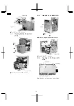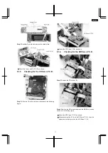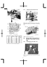
8.3. Main Component Replacement
Procedure
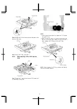
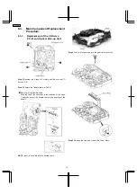
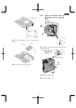
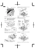
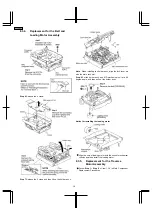
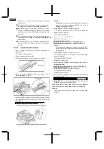
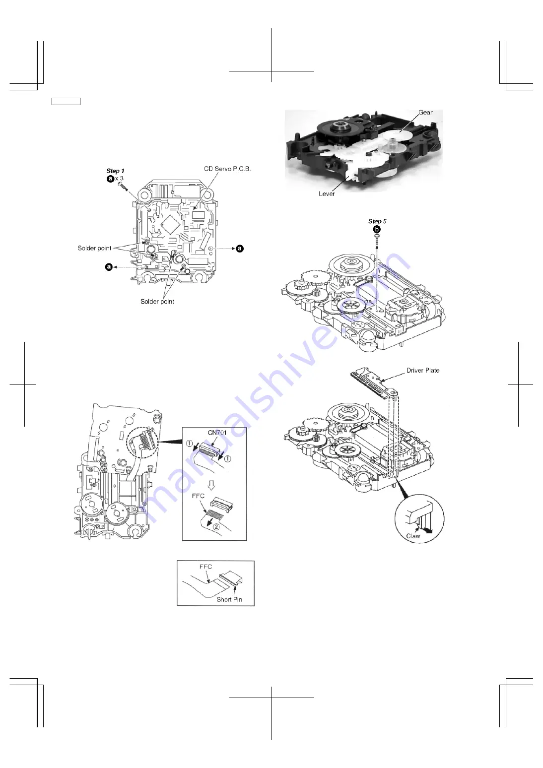
8.3.1. Replacement of the CD Servo
P.C.B. and Optical Pick-up Unit.
Step 2 Desolder the 4 legs of 2 motors and flip over the CD
Servo P.C.B.
Step 3 Remove the flexible cable at CN701.
•
Removal of the flexible cable
Push the top of the connector in the direction of the arrow
1 and then pull out the flexible cable in the direction of the
arrow 2.
NOTE : Insert a short pin into the flexible cable.
Step 4 Push the lever in and turn the gear clock wise fully.
Step 6 Release the claw and remove the Driver Plate.
14
SA-PM30MD
Summary of Contents for SA-PM30MD
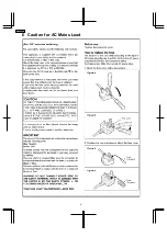
Page 6: ...6 Caution for AC Mains Lead 6 SA PM30MD ...
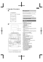
Page 7: ...7 Operation Procedures 7 SA PM30MD ...
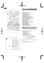
Page 8: ...8 SA PM30MD ...
Page 74: ...16 Wiring Connection Diagram 74 SA PM30MD ...
Page 75: ...17 Troubleshooting Guide 75 SA PM30MD ...
Page 76: ...76 SA PM30MD ...
Page 77: ...77 SA PM30MD ...
Page 78: ...78 SA PM30MD ...
Page 79: ...79 SA PM30MD ...
Page 80: ...80 SA PM30MD ...
Page 81: ...81 SA PM30MD ...
Page 82: ...82 SA PM30MD ...
Page 84: ...18 1 1 Deck Mechanism Parts Location 18 1 Deck Mechanism RAA4106 84 SA PM30MD ...
Page 86: ...18 2 MD Mechanism 18 2 1 MD Mechanism Parts location 86 SA PM30MD ...
Page 88: ...18 3 CD Loading Mechanism 18 3 1 CD Loading Mechanism Parts Location 88 SA PM30MD ...
Page 90: ...18 4 1 Cabinet Parts Location 18 4 Cabinet 90 SA PM30MD ...
Page 91: ...91 SA PM30MD ...


