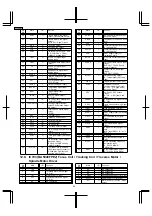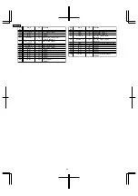
<Cassette Deck>
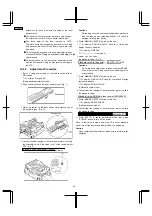
Fig. 8
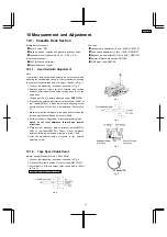
Adjust each laser power : read power for reading (play) and
write power for writing (record).
10.4.1. Necessary Instruments
•
Laser power meter (Advantest TQ8210 or compatible
meter)
•
Test disc (Pre-mastered disc RFKV0006 or RFKV0014)
•
Recordable disc available on sales root (with music
recorded)
•
Insulated driver for adjustment such as a ceramic driver
•
Jitter meter
10.4.2. Set the Unit to the Adjustment
Mode
1. Perform the item “8.1.6. Checking for the MD Servo P.C.B.”
in “Operation Check and Main Component Replacement
Procedures”, Step 1 to Step 4.
2. Turn the power on.
3. Press CD play button with no CD, cassette or MD loaded.
4. Press and hold the STOP button for at least 2 seconds, and
while still pressing the STOP button, press the Forward
Skip/Search button for at least 2 seconds. The unit enters
Self-Diagnostic Mode and display “TEST”.
5. While pressing STOP button on the unit, press 4 and 7 on
the remote control. The unit enters doctor mode for
adjustment.
Cautions
1. About handling the MD unit
•
The magnetic head is a precision unit and is very
<Tuner>
Fig. 9
Fig. 10
fragile. Do not deform it.
•
Laser diode in the optical pickup may be destroyed
by the staticelectricity generated in your clothes or
body. Be especially careful with the static electricity.
•
The optical pickup is structured extremely precisely.
Do not subject to the strong impact or shock. Do not
touch the lens.
2. About handling the magnetic head
When replacing the magnetic head, do not tighten the
mounting screw (RHD17022) too firmly. If the screw is
tightened too much to deform the resin, the position of
the head is moved, and this affects its recording
operation.
Recommended torque for mounting screw: 700 g cm +/-
100 g cm
Reference:
This
is the same
force
as using
a
screwdriver with a 15-mm diameter grip, you fasten the
screw naturally with your thumb and index finger.
3. About the driver for adjusting laser power
Use only insulated driver such as a ceramic driver. With
the metal driver, it is not possible to adjust properly
because of the induction noise. Also, if it short-circuits
with the chassis, it may destroy or damage the laser
diode.
Recommended driver: VESSEL 9000 1.8 -30 (Ceramic
driver)
Cautions on optical pickup:
•
The
optical
pickup
and
the
magnetic
head
are
structured precisely; therefore, they are very fragile. Be
10.3. Alignment Points
10.4. Laser Power Adjustment
23
SA-PM30MD
4. While pressing STOP on the unit, press 4 followed by
7 on the remote. Display will now show CD E no disc,
MD E no disc or TAPE E (E is shown by 3 horizontal
bars)
5. Pressing STOP will toggle between these displays.
With MD E no disc in the display, continue with 10.4.3.
Summary of Contents for SA-PM30MD
Page 6: ...6 Caution for AC Mains Lead 6 SA PM30MD ...
Page 7: ...7 Operation Procedures 7 SA PM30MD ...
Page 8: ...8 SA PM30MD ...
Page 74: ...16 Wiring Connection Diagram 74 SA PM30MD ...
Page 75: ...17 Troubleshooting Guide 75 SA PM30MD ...
Page 76: ...76 SA PM30MD ...
Page 77: ...77 SA PM30MD ...
Page 78: ...78 SA PM30MD ...
Page 79: ...79 SA PM30MD ...
Page 80: ...80 SA PM30MD ...
Page 81: ...81 SA PM30MD ...
Page 82: ...82 SA PM30MD ...
Page 84: ...18 1 1 Deck Mechanism Parts Location 18 1 Deck Mechanism RAA4106 84 SA PM30MD ...
Page 86: ...18 2 MD Mechanism 18 2 1 MD Mechanism Parts location 86 SA PM30MD ...
Page 88: ...18 3 CD Loading Mechanism 18 3 1 CD Loading Mechanism Parts Location 88 SA PM30MD ...
Page 90: ...18 4 1 Cabinet Parts Location 18 4 Cabinet 90 SA PM30MD ...
Page 91: ...91 SA PM30MD ...

