4
1.2.
Before Repair and Adjustment
Disconnect AC power & discharge AC Capacitors (C5700, C5701, C5702, C5705 and C5706) through a 10W, 1W resistor to
ground.
Caution : DO NOT SHORT-CIRCUIT DIRECTLY (with a screwdriver blade, for instance), as this may destroy solid state devices.
After repairs are completed, restore power gradually using a variac, to avoid overcurrent.
• Current consumption during AC 220V ~ 240V, at 50Hz in NO SIGNAL mode (at volume minimum in FM mode) should be ~200
mA.
1.3.
Protection Circuitry
The protection circuitry may have operated if either of the following conditions are noticed:
• No sound is heard when the power is turned on.
• Sound stops during a performance.
The function of this circuitry is to prevent circuitry damage if, for example, the positive and negative speaker connection wires are
"shorted", or if speaker systems with an impedance less than the indicated rated impedance of the amplifier are used.
If this occurs, follow the procedure outlines below:
1. Turn off the power.
2. Determine the cause of the problem and correct it.
3. Turn on the power once again after one minute.
Note:
When the protection circuitry functions, the unit will not operate unless the power is first turned off and then on again.
1.4.
Caution For Fuse Replacement
1.5.
Safety Part Information
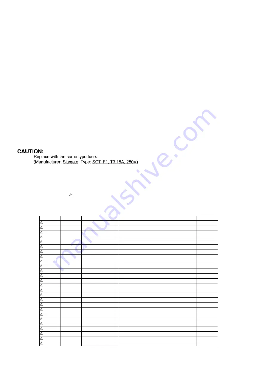
Safety Parts List:
There are special components used in this equipment which are important for safety.
These parts are marked by in the Schematic Diagrams, Exploded View & Replacement Parts List. It is essential that these
critical parts should be replaced with manufacturer’s specified parts to prevent shock, fire or other hazards. Do not modify the
original design without permission of manufacturer.
Safety
Ref. No.
Part No.
Part Name & Description
Remarks
12
RGR0474D-A1
REAR CABINET
16
RKM0766A-S
TOP CABINET
23
RMQ2463
SMPS PC SHEET
301
RAE1047Z-V
TRAVERSE ASS’Y
(E.S.D)
A2
K2CQ2YY00119
AC CORD
A3
RQT9992-1D
O/I BOOK (Ge/It/Fr/Du/Da/Sw/Fi)
A3
RQT9993-1E
O/I BOOK
A3
RQT9994-1R
O/I BOOK (Po/Cz/Sp)
A3
RQT9995-1B
O/I BOOK (En)
PCB6
REP5161AA
SMPS P.C.B
(RTL)
DZ5701
D4EAY5110006
SURGE ABSORBER
L5704
G0B203G00005
LINE FILTER
L5713
G0B922G00002
LINE FILTER
T5701
G4DYZ0000080
SWITCHING TRANSFORMER
PC5721
B3PBA0000579
PHOTO COUPLER
PC5761
B3PBA0000579
PHOTO COUPLER
F1
K5G312Y00007
FUSE
P5701
K2AA2B000011
AC INLET
R5700
D0GF474JA048
470K 1/4W
R5701
D0GF474JA048
470K 1/4W
R5710
D0GF474JA048
470K 1/4W
C5700
F1BAF1020020
1000pF
C5701
F0CAF224A105
0.22uF
C5702
F0CAF224A105
0.22uF
C5705
F1BAF1020020
1000pF
C5706
F1BAF1020020
1000pF
Summary of Contents for SA-PMX100
Page 10: ...10 5 Location of Controls and Components 5 1 Main Unit Remote Control Key Button Operations ...
Page 21: ...21 8 3 Main Parts Location Diagram ...
Page 44: ...44 ...
Page 50: ...50 ...
Page 52: ...52 ...
Page 64: ...64 ...


