background image

53

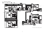
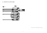
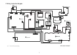
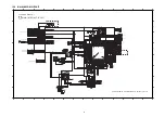
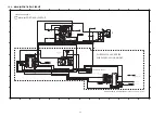
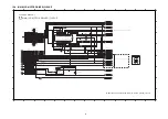
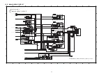
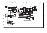
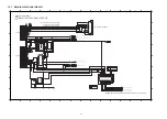
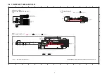
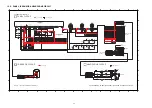
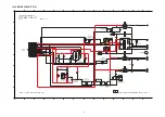
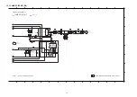
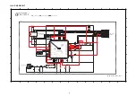
12.2. MAIN (MICON) CIRCUIT

A

1

2

3

4

5

6

7

8

9

10

11

1

2

13

14

1

2

3

4

5

6

7

8

9

10

11

1

2

13

14

C

D

B

E

G

H

F

A

C

D

B

E

G

H

F

A

SA

-PMX150EG/PC, 

SA

-PMX15

2

EG 

M

A

IN (MICON) CIRCUIT

 M

A

IN (MICON) CIRCUIT

S

CHEM

A

TIC DI

A

GR

A

M - 1

TRDRV

PCONT3

ECO_CTL

I2S_BCK

AC_SYNC

SMPS_ID

DC_DET_PWR

LOT26_CTRL

NETWORK_PCONT

I2S_SDO0

DC_DET_AMP

DSP_ERR

DSP_SCL

DSP_SDA

DSP_ERR

DSP_MUTE

HP_MUTE

DAMP_MUTE

DSP_RESET

I2S_LRCK

TRVDRV

SPDRV

LD_CW

LD_CCW

VBIAS

F

C

D

B

A

E

FODRV

LDO

MD

AGND1

BT_UART_TX

CLK_TUN_BCK

PW_D3R3V

FL_RESET

CLK_TUN_SDO

CLK_TUN_LRCK

PW_USB5R2V

VHGND

PW_VH

PW_5R6V

PW_STBY1R55V

AUX_RCH

$[D0GAR00J0005]

R8375

4

3

1

2

L8000

EXC24CE900U

DGND

PW_STBY3R3V

PW_D3R3V_SOC

CK8025

CK8026

CK8027

F1H1H104B047

C8121

50V

F1H1H104B047

C8152

50V

J0JYC0000656

LB8016

CK8023

CK8024

CK8022

CK8021

TU_RST

CLK_TU_SDA

CLK_TUN_BCK

CLK_TUN_LRCK

R8216

D0GB151JA065

LB8026 J0JGC0000063

F1G1C104A146 C8359

16V

R8279

D0GB330JA065

CLK_TUN_SCL

TU_INT

J0JYC0000656

LB8027

R8280

D0GB330JA065

CK8028

CK8029

CK8031

CK8030

R8217

D0GB151JA065

CLK_TUN_SDO

*

C8357

C8358

*

R8215

D0GB151JA065

J0JYC0000656

R8329

J0JYC0000656

R8330

J0JHC0000118

R8326

D0GBR00J0004

R8327

BASS_JOGB

TREBLE_JOGA

BASS_JOGA

J0JYC0000656

R8334

*

R8434

*

R8455

F1G1C104A146

C8340

16V

F1G1C104A146

C8341

16V

J0JYC0000656

R8331

KEY1

TREBLE_JOGB

VOL_JOG

KEY2

REM_IN

F1G1C104A146

C8344

16V

F1G1C104A146

C8360

16V

F1H1H104B047

C8342

50V

C8276

F1H1H104B047

50V

J0JYC0000656

R8332

R8214 D0GBR00J0004

J0JGC0000063 LB8010

FL_RESET

FL_DO

CLK_FL

C8343

F1G1C104A146

16V

FL_CS

CK8010

CK8013

CK8012

CK8011

CK8002

CK8005

CK8007

CK8009

CK8008

CK8006

CK8003

CK8004

C8275

F1H1H104B047

50V

J0JYC0000656

R8333

J0JGC0000063

LB8019

J0JGC0000063

LB8021

D0GB101JA065

R8211

*

R8268

D0GB101JA065

R8213

D0GB101JA065

R8212

CK8017

CK8018

CK8020

CK8019

CK8016

CK8015

J0JYC0000656

R8335

F1H1H104B047

C8252

50V

CK8014

18

16

14

8

9

11

12

10

2

3

1

5

7

6

4

13

15

17

19

K1MY19AA0267

CN8001

J0JYC0000656

R8336

AUX_LCH

DGND

PW_D3R3V_SOC

PW_STBY3R3V

CK8032

CK8033

7

9

11

10

12

8

2

3

1

5

6

4

13

CN8008

*

AUX_GND

LD_CW

F1G1C104A146

C8024

16V

R8066

D0GB153JA065

R8067

D0GB683JA065

DSP_SCL

DSP_SDA

D0GB222JA065

R8007

DSP_RESET

HP_MUTE

DSP_ERR

DC_DET_AMP

DSP_MUTE

DAMP_MUTE

DSP_ERR

R8009

$[D0GB103JA065]

R8004

D0GBR00J0004

F1H1H103B047

C8068

50V

LD_CCW

LB8003

J0JYC0000656

LOT26_CTRL

D0GB104JA065

R8454

PCONT

PCONT

SMPS_LATCH

AC_SYNC

SMPS_ID

NETWORK_PCONT

PCONT3

ECO_CTL

SMPS_LATCH

C8353

F1H1H104B047

50V

C8352

50V

NRST

F1G1C104A146

C8266

16V

5

6

1

3

4

2

8

7

CN8000

K1MN08AA0046

LB8022

J0JYC0000656

C8025

F1H0J1060006

6.3V

C8334

F1H0J1060006

6.3V

C8348

50V

C8349

50V

J0JCC0000317

LB8028

J0JCC0000317

LB8029

8

6

5

7

4

2

1

3

D1H82214A042

RX8011

R8050

D0GB104JA065

6

5

8

7

3

4

1

2

J0JBD0000050

RX8009

C8064

F1H1H104B047

50V

J0JYC0000656

LB8018

F1G1C104A146

C8339

16V

F1H1H104B047

C8260

50V

D0GB222JA065

R8008

6

7

T1

5

2

4

3

8

ThermalPad

1

IC8005

MFI337S3959

J0JHC0000118

LB8009

2

1

7

85

4

3

6

IC8003

*

F1H1C104A178

C8031

16V

LB8004

J0JYC0000656

PW_D3R3V_SOC

F1H0J1060006

6.3V

C8032

DC_DET_PWR

*

R8452

LB8030

J0JYC0000656

C8335

F1G1C104A146

16V

R8047

D0GB101JA065

D0GB101JA065

R8046

R8437

D0GB101JA065

R8438

D0GB101JA065

R8451

*

$[F1G1C104A146]

C8267

C8030

F1G1C104A14616V

C8029

F1H1H101B05250V

R8374

D0GB101JA065

LB8008

J0JYC0000656

F1H1H104B047

C8063

50V

LB8006

J0JYC0000656

R8444

D0GA101JA023

R8445

D0GA101JA023

C8036

F1H0J1060006

6.3V

C8035

F1G1C104A146

16V

F1G1C104A146

C8332

16V

C8033

F1G1C104A146

16V

USB_FAULT

FL_RESET

NETWORK_PCONT

BASS_JOGB

BASS_JOGA

LOT26_CTRL

CL8014

CL8042

CL8043

R8223

D0GB104JA065

CL8038

CL8037

D0GB104JA065

R8005

R8051

D0GB103JA065

R8052

D0GB103JA065

6

5

8

7

3

4

1

2

RX8008

J0JBD0000050

R8000

D0GA101JA023

D0GB101JA065

R8003

C8001

F1H1C104A178

16V

D0GA101JA023

R8436

F1H1C104A178

C807016V

C8050

F1G1H101A834

50V

D0GA101JA023

R8435

F1G1C104A146

C8002

16V

C8049

F1G1H101A834

50V

R8092

R8093

J0JYC0000656

LB8031

CLK_TU_SDA

CLK_TUN_SCL

R8339

D0GA101JA023

CL8054

J0JYC0000656

LB8017

CL8055

D0GB222JA065

R8321

R8312

D0GA101JA023

8

6

5

7

4

2

1

3

D1H81014A042

RX8020

R8310

D0GA101JA023

F1G1H101A834

C8257

50V

F1H0J4750004

C8258

6.3V

J0JYC0000656

LB8024

8

6

5

7

4

2

1

3

RX8019

*

OPEN_SW

IO_EXP_CLR

C8028

$[F1H1H331B052]

G_MR_RESET

ALL_SELALL_SEL

ALL_ASYNC_RESET

USB_SEL

C8027

$[F1H1H331B052]

IO_EXP_STB

IO_EXP_CLK

IO_EXP_DATA

CLOSE_SW

C8337

F1G1C104A146

16V

R8290

$[D0GB103JA065]

F1G1C104A146

C8336

16V

C8263

F1H0J1060003

6.3V

C8259

F1G1C104A146

16V

C8026

F1H1H223B047

50V

F1H1H104B047

C8345

50V

F1G1H101A834

C8256

50V

F1G1H101A834

C8255

50V

R6014

D0GAR00J0005

D0GB222JA065

R8432

USB_2D-

4

3

1

2

L6000

$[EXC24CE900U]

D1BB1002A074

R8441

2

G2

1

4

G1

3

CN6004

K1FB104B0064

ALL_UART_TX

ALL_UART_RX

R8083

D0GA101JA023

R8350

*

R8349

*

C8038

F1H1H101B052

50V

R8117

D0GB106JA065

D0GB224JA065

R8088

F1G1C104A146

C8338

16V

TREBLE_JOGB

R8085

D0GB152JA065

CL8057

CL8058

C8041

F1H1H100B051

50V

REM_IN

ALL_UART_RX

ALL_UART_TX

D0GA101JA023

R8089

DSP_SDA

DSP_SCL

C8040

F1H1H220B052

50V

C8039
F1H1H220B052

50V

H0A327200191

X8002

C8270

F1H1H104B047

50V

J0JYC0000656

LB8023

MD1

BT_PCONT

I2S_SEL_3

ADC_PON

8

6

5

7

4

2

1

3

RX8021

D1H81014A042

CL8059

CL8056

CL8060

8

6

5

7

4

2

1

3

RX8022

D1H81014A042

BT_WAKE

R1163

$[D1BA2002A022]

C1166

F1H1H104B047

50V

D1BA1802A022

R1162

F1H1H104B047

C8356

50V

C1165

F1H1H104B047

50V

F1J1A106A043

C1164

10V

R1168
D0GB103JA065

USB_FAULT

D0GA101JA023

R1170

R1169

D0GB153JA065

CK8046

CK8045

RL1101

D0GB680JA065

R8464

F1H1H101B052

C8361

50V

C1167

F1H1H104B047

50V

8

6

5

7

4

2

1

3

D1H81014A042

RX1100

PW_USB5R2V

D0GB103JA065

R1166

CLT3

USB_ENABLE

CLT1

12

1

16

T1

13

15 14

0

1

3

6 7

8

5

9

4

11

2

Thermal

Pad

IC1113

C1ZBZ0005438

R1164

D0GB103JA065

PW_USB5R2_1

CK8043

CK8044

R1165

D0GBR00J0004

CK_CONN

CK_USBA_D-_CONN

C1168

F1H1H102B047

50V

2

4

3

1

G1

6

7

5

G2

CN1101

K1KA07AA0714

R6015

D0GAR00J0005

NRST

D0GBR00J0004

R8463

D0GBR00J0004

LB8033

R8094

C8042

F1H1H100B051

50V

G_MR_RESET

ALL_SEL

ALL_ASYNC_RESET

ALL_ASRC_MUTE

CHASSIS_GND

$[EZAEG2A50AX]

VA8201

R8443

D1BB2202A074

C8329

F1H1A225A102

10V

C8330

F1G1A1050004

10V

$[EZAEG2A50AX]

VA8200

C8328

F1H1H102B047

50V

R8439

D0GBR00J0004

C8327

F1H1H102B047

50V

1

4

2

3

C0EBY0000664

IC8002

F1H1C224A178

C8067

16V

C8043

F1H1H104B047

50V

21

23

6

7

18

20

19

21

4

5

13

12

10

8

9

17

15

16

11

14

3

22

24

C0JBAZ003040

IC8006

21

7

8

5

4

3

6

IC8004

C3EBHY000039

2

3

1

4

X8001

H0J169500045

R8090

D0GB105JA065

D0GA681JA023

R8091

C8271

F1G1C104A146

16V

C8037

F1G1H102A834

50V

C8268

F1G1C104A146

16V

BT_UART_RTS

CK8035

CK8034

BT_UART_RTS

USBB_VBUS

SMPS_LATCH

AC_SYNC

DSP_RESET

C8355

F1H1H104B047

50V

8

6

5

7

42

1

3

D1H81014A042

RX8015

F1G1H101A834

C8052

50V

F1G1H101A834

C8269

50V

F1G1H101A834

C8053

50V

C8354

F1H1H104B047

50V

$[D0GAR00J0005]

R8376

BT_UART_RX

R8152

D0GB330JA065

D0GB330JA065

R8151

LB8014

J0JYC0000656

CK8042

CK8039

CK8041

CK8040

CK8037

J0JYC0000656

LB8011

CK8036

J0JYC0000656

LB8012

C8150

F1H1H104B047

50V

CK8038

3

2

6

7

4

5

1

9

8

K1KA09AA0193

CN8003

J0JYC0000656

LB8013

TREBLE_JOGA

DC_DET_AMP

DSP_MUTE

D0GA101JA023

R8082

R8084

D0GB152JA065

USB_1D-

PCONT3

ECO_CTL

PCONT

DSP_ERR

R8351

D0GA101JA023

BT_HOST_WAKE

8

6

5

7

42

1

3

D1H81014A042

RX8018

6

5

1

10

3

4

2

8

9

7

IC8008

C0JBAS000450

8

6

5

7

42

1

3

D1H81014A042

RX8017

D0GB104JA065

R8453

J0JYC0000656

LB8025

USBB_VBUS

8

6

5

7

42

1

3

RX8016

D1H81014A042

F1G1C104A146

C8326

16V

CLK_D+

CLK_D-

USB_SEL

BT_HOST_WAKE

BT_WAKE

BT_UART_TX

BT_UART_RX

PW_BT_5V

R8036

*

F1G1H472A571

C8010

50V

R8041

*

CL8009

CL8010

F1H1H472B047

C8011

50V

C8012

F1H1C104A178

16V

F1H1H472B047

C8013

50V

D0GB103JA065

R8044

R8034

D0GA101JA023

KEY1

KEY2

R8440

D0GA101JA023

SMPS_ID

VOL_JOG

F1H1H102B047

C8014

50V

F1H1H102B047

C8015

50V

R8224

D0GB101JA065

8

6

5

7

4

2

1

3

RX8013

D1H81014A042

C8347

F1H1H104B047

50V

F1H0J1060006

C8007

6.3V

C8009

F1H0J1060006

6.3V

D0GB103JA065

R8043

D0GB103JA065

R8033

D0GB103JA065

R8042

F1H1H104B047

C8350

50V

LB8001

J0JYC0000656

R8218

D0GB184JA065

R8210

D0GB474JA065

D0GB103JA065

R8220

B1ABCF000176

Q8000

D0GA103JA023

R8030

C8060

F1G1H101A834

50V

C8008

F1G1C104A146

16V

D0GA103JA023

R8031

R8029

D0GBR00J0004

D0GB103JA065

R8032

C8351

F1H1H104B047

50V

LB8000

J0JYC0000656

HP_MUTE

DAMP_MUTE

LD_CCW

LD_CW

D0GA101JA023

R8287

8

6

5

7

4

2

1

3

D1H81014A042

RX8002

INNER_SW

HP_DET

D0GB472JA065

R8292

R8026

D0GB472JA065

R8338

D0GA101JA023

R8341

D0GB223JA065

TU_INT

TU_RST

I2S_SEL_1

CL8040

I2S_SEL_4

CL8041

D8000

DB2J31400L

FL_DO

CLK_FL

ALL_ASRC_MUTE

F1G1C104A146

C8273

16V

C8272

F1G1C104A146

16V

FL_CS

CL8031

F1H0J1060006

C8333

6.3V

C8051

$[F1G1H101A834]

$[F1G1H101A834]

C8047

C8346

F1H1H104B047

50V

8

6

5

7

4

2

1

3

RX8001

D1H81014A042

C8048

F1G1H101A834

50V

F1G1C104A146

C8003

16V

F1H0J1060006

C8004

6.3V

F1G1H102A834

C8059

50V

C8005

F1H1H101B052

50V

C8006

F1H1H101B052

50V

R8024

D0GA104JA023

R8028

D0GA104JA023

R8025

D0GA104JA023

R8340

D0GA104JA023

R8291

D0GB103JA065

LB8032

J0JYC0000656

8

6

5

7

4

2

1

3

RX8003

D1H81014A042

R8115

D0GB683JA065

C8044

F1H1H222B047

50V

D0GB683JA065

R8116

C8045

F1H1H222B047

50V

C8021

F1H1C104A178

16V

R8045

D0GB471JA065

C8020

F1H1C104A178

16V

C8022

F1H1A335A083

10V

C8023

F1H1C224A178

16V

C8362

F1J1A106A043

10V

D0GBR00J0004

R8355

CL8011

CL8012

C8016 F1G1H681A571

50V

CL8013

PW_STBY3R3V

31

66

2

3

1

8

9

5

4

7

6

29

68

15

17

24

23

26

27

25

19

18

21

22

20

16

10

12

14

13

11

70

73

75

77

80

79

81

82

Thermal

Pad

78

76

74

72

92

91

94

96

95

T1

120

126

125

128

127

122

121

124

123

110

111

98

97

99

107

102

100

101

105

106

103

104

109

108

117

118

115

116

119

113

112

114

93

85

86

83

84

88

90

89

87

71

28

69

30

67

32

65

60

59

61

57

58

63

64

62

51

52

49

50

54

56

55

53

40

42

41

36

35

37

33

34

39

38

45

47

48

46

43

44

IC8001

C1AB00004475

8

6

5

7

4

2

1

3

D1H81034A042

RX8005

F1J1A106A043

C8019

10V

D0GB100JA065

R8442

C8017

F1J1A106A043

10V

C8331

F1J1A106A043

10V

C8018

F1G1C104A146

16V

TDI

TCK

TMS

GND

RESET

put near SoC

Eject & Power Connected to KEY2

TDO

TRST

TO DSP/DAMP

TO CD DRIVER

IC

Guard I2S_BCK and I2S_LRCK line with GND

STNDBY_3R3V

TO MAIN POWER SUPPLY

FOR JTAG

PROGRAMMING

PMX70/100 mechanism use TRV_CW & TRV_CCW

shield A_B_C_D_E_F signal with AGND1

TO DSP/DAMP

FL_DO

TU_INT

FL_CLK

ASRC_MUTE

DAMP_MUTE

HP MUTE

TU_RST/DAB_RST

VSSQ

VDDQ

DVSS

VBUS

D-

TO ALLPlay MODULE

DVDD_HV

DGND

XIN_32K

D+

RESETX

DVDDIO

OPEN_SW

EE_SCL

EE_SDA

IO_EXP_CLK

IO_EXP_DATA

HP_DET

IO_EXP_CLR

IO_EXP_STB

CLOSE_SW

TUNER_SDA/DAB SDA

TUNER_SCL/DAB_SCL

DVSS

FL_CS

DVDD_LV (1.6V)

DVSS

d+ d- differential

impedance 90 ohm

D-

DGND

caution

DGND

LOCATION TOP PCB

CHASSIS SCREW POINT

D+

USB A (FRONT)

FROM USB SUB PCB

Minimum 2.1mm Pattern width

DGND

TO USB SUB PCB

USB5V

USB5V

IN

OUT

ILIM_LO

TPS2543

FLT

GND

Minimum 2.1mm Pattern width

ILIM_HI

DP_OUT

EN

CLT1

ILIM_SEL

DM_OUT

/STS

CLT3

CLT2

DM_IN

DP_IN

d+ d- differential

impedance 90 ohm

To chassis GND

USB A (FRONT)

P15

P14

P16

SO

A1

A0

A2

GND

P8

P7

P12

P11

VSS

P13

P10

P9

STB

CLR

CLK

DATA

To HP (@ DSP)

VCC

SCL

WP

SDA

EEPROM IC

Guard CLK_FL and CLK_TU_SCL line with GND

P3

P4

P1

P2

P6

P5

VSS

RX8019 is for PMX150 ONLY

NOTE

VDD

To MAIN SUPPLY BT

Delay time: 0.69*RD*CD

(RD=9M Ohm - 11M Ohm)

To Selector 3 (@ ADC)

To ADC

To ADC

CD

VIN

VOUT

GND

NC

JTAG TRST

JTAG TDI

D=2D

Function

D=1D

differential impedance 90 ohm

2D+

GND

2D-

1D-

1D+

D+

D-

USB_SEL

/OE

VCC

GND

GND

BT_CTS

BLUETOOTH

CONNECTOR RDA

BT_WAKE

PW_BT_5V

USB_B

USB_A

H

L

Sel

L

H

OE

Truth Table

HOST_WAKE

BT_UART_TX

GND

BT_UART_RX

FROM MAIN SUPPLY

MOUNT NEAR THE SOC IC (FOR ESD)

NOTE FOR FLASH IC

Route D+ & D- and NO cross each other

KEY2

PANEL CONNECTOR

KEY1

DGND

VH

TREBLE_JOG_B
REM_IN

BASS_JOG_B

TREBLE_JOG_A

NOTE:

ALL model will use R8434 5.6V SUPPLY

FROM MAIN SUPPLY

FROM MAIN SUPPLY

FLVHGND

PW_STBY3.3V

FL+_PW_5.6V

VOL_JOG

TUNER & DAB

For DAB:   10Pins (K1MN10AA0046)

NOTE: SMT CONNECTOR

For Non DAB: 13Pins (K1MN13AA0046)

DGND

AGND

DGND

TUNER I2S DATA

RESET

DGND

AUX LCH

To ADC

To Main Supply

To Selector 3 (p2,p5,p11)@ ADC

Guard CLK_TU_SCL line with GND

Guard CLK_TUN_BCK and CLK_TUN_LRCK line with GND

FROM MAIN SUPPLY

FL_DATA

FL_CS

SCLK/DAB_RX

FL_RESET

NC/TUNER INT

AUX RCH

CLK_TUN/DAB_BCK

CLK_TUN/DAB_LRCK

CLK_TUN/DAB_DATA

PW_D3.3V

SDIO/DAB_TX

D3.3V_SOC

BASS_JOG_A

FL_CLK

Guard CLK_FL line with GND

TREBLE_JOGB

DSP_SDA/NFC_SDA

DSP_SCL/NFC_SCL

REM_IN

ALL_UART_TX

ALL_UART_RX

ECO_CTL

CLK

VCC

VSS

DVSS

DVDD_HV

DC_DET_PWR

I2S LRCK

I2S BCK

DVDD_HV

I2S DATA

BASS_JOGA

BASS_JOGB

LOT26_CTRL

CPIC_SCLK

CPIC_DATA

FL_CS

DVSS

NC

FL_DAT1

FL_DAT3

FL_DAT2

FL_DAT0

DVDD_M2

FL_CLK

DSP_ERR

DVDD[96]

USB_FAULT[95]

FL_RESET[94]

NETWORK_PCONT[93]

NC

I2C_SCL

RESET

CP IC

NC

VSS

I2C_SDA

VCC

DI(DQ0)

VSS

FLASH IC

HOLD#(DQ3)

CS#

DO(DQ1)

WP#(DQ2)

DSP_MUTE
TREBLE_JOGA

BM94803EKU

DAMP_OTW/DC_DET_AMP/DAMP_SD

USB_B_VBUS

DVSS

BT_UART_TX

BT_UART_RTS

BT_UART_CTS

REXTI

USB D+

USB D-

BT_UART_RX

DSP_RESET

AC_SYNC

SMPS_LATCH

BT_HOST_WAKE

For PMX150 --> C3FBNY000362 (32MB)

For PMX80 --> C3FBMY000303 (16MB)

PCONT

PCONT3

USB B (REAR)

differential impedance 90 ohm

for D+ and D- signal

DVSS

For log

data

XOUT_PLL[128]

XIN_PLL[127]

TMODE[126]

XOUT_32K[125]

LD_CCW

LD_CW

put near SoC

NC

MAIN_KEY_INT

REGION

VOL_JOG

MODEL_SELECT

RFI

EQO

AD_MONI0

AD_MONI1

VSS_ADC

SMPS_ID

ANAMONI1

ANAMONI0

INNER_SW

KEY2[35]
KEY1[34]

VDD_ADC[33]

1.6V_Det[36]

To Selector 1 (@ DSP)

To Selector 4 (@ DSP)

CLVOUT

E

F

BD

VBIAS

AGND1

AC

PD

PCO

FCO

LD

ASY

AVDD1

SDOUT

TDOUT

FDOUT

JTAG TMS[68]

JTAD TCK[67]

JTAG TDO[66]

CLK88[65]

Summary of Contents for SA-PMX152EG

Page 1: ...7 2 4 Handling Precaution for Traverse Unit 8 3 Service Navigation 9 3 1 Service Information 9 3 2 Software Firmware Update 9 4 Specifications 10 5 Location of Controls and Components 12 5 1 Main Unit Remote Control Key Button Operations 12 6 Service Mode 13 6 1 Service Mode Table 13 6 2 Service Mode Error Code 14 6 3 Doctor Mode 15 6 4 Sales Demonstration Lock Function Mode 18 7 Troubleshooting G...

Page 2: ... BLOCK DIAGRAM 48 11 Wiring Connection Diagram 49 12 Schematic Diagram 51 12 1 Schematic Diagram Notes 51 12 2 MAIN MICON CIRCUIT 53 12 3 MAIN MPORT ADC CIRCUIT 54 12 4 MAIN CD MOTOR DRIVER CIRCUIT 55 12 5 MAIN SUPPLY CIRCUIT 56 12 6 MAIN DSP DAMP HEADPHONE CIRCUIT 57 12 7 MAIN ALLPLAY LAN CIRCUIT 58 12 8 CD INTERFACE TUNER USB CIRCUIT 59 12 9 PANEL IR SENSOR HEADPHONE CIRCUIT 60 12 10 SMPS CIRCUI...

Page 3: ...hafts etc When the exposed metallic part has a return path to the chassis the reading should be between 1MΩ and 5 2MΩ When the exposed metal does not have a return path to the chas sis the reading must be 1 1 2 Leakage Current Hot Check 1 Plug the AC cord directly into the AC outlet Do not use an isolation transformer for this check 2 Connect a 1 5kΩ 10 watts resistor in parallel with a 0 15μF cap...

Page 4: ...s to prevent shock fire or other hazards Do not modify the original design without permission of manufacturer Safety Ref No Part No Part Name Description Remarks 12 RGR0474M A REAR CABINET 150PCS 12 RGR0474M B REAR CABINET 150EGS 12 RGR0474N A REAR CABINET 152EGS 48 RFKKMX100EGS TOP AL ORNAMENT ASS Y 301 TXQ0011 TRAVERSE ASS Y E S D A2 K2CB2YY00065 AC CORD 150PCS A2 K2CQ2YY00107 AC CORD 150EGS 152...

Page 5: ...solder or unsolder ES devices 4 Use only an anti static solder removal device Some solder removal devices not classified as anti static ESD protected can generate electrical charge sufficient to damage ES devices 5 Do not use freon propelled chemicals These can generate electrical charges sufficient to damage ES devices 6 Do not remove a replacement ES device from its protective package until imme...

Page 6: ...ng time ACHTUNG Dieses Produkt enthält eine Laserdiode Im eingeschalteten Zustand wird unsichtbare Laserstrahlung von der Lasereinheitadg estrahit Wellenlänge 790nm CD Maximale Strahlungsleistung der Lasereinheit 100 μW VDE Die Strahlung an der Lasereinheit ist ungefährlich wenn folgende Punkte beachtet werden 1 Die Lasereinheit nicht zerlegen da die Strahlung an der freigelegten Laserdiode gefähr...

Page 7: ...is used Definition The letter of PbF is printed on the PCB using the lead free solder To put lead free solder it should be well molten and mixed with the original lead free solder Remove the remaining lead free solder on the PCB cleanly for soldering of the new IC Since the melting point of the lead free solder is higher than that of the normal lead solder it takes the longer time to melt the lead...

Page 8: ...xible cable of the optical pickup unit removed should be short circuited with a short pin or a clip 3 The flexible cable may be cut off if an excessive force is applied to it Use caution when handling the flexible cable 4 The antistatic FFC is connected to the new optical pickup unit After replacing the optical pickup unit and connecting the flexi ble cable cut off the antistatic FFC Figure 2 2 2 ...

Page 9: ...UNER P C B Change by component 4 DAB P C B Change by component 5 USB P C B Change by component 6 PANEL P C B Change by component 7 IR SENSOR P C B Change by component 8 HEADPHONE P C B Change by component 9 SMPS P C B Change by component 10 BLUETOOTH P C B Change by P C B exchange 11 ALLPLAY MODULE with Data Change by P C B exchange 12 ALLPLAY ANTENNA P C B Change by P C B exchange Detective P C B...

Page 10: ...Hz Audio word size 16 bits Channel count 2 ch AIFF FLAC 5 WAV Sampling frequency 32 44 1 48 88 2 96 176 4 192 kHz Audio word size 16 bits 24 bits Channel count 2 ch DSD 2 8 MHz 5 6 MHz USB device file system FAT12 FAT16 FAT32 PC IN EXT IN 6 Terminal Type USB B USB standard USB 2 0 High Speed USB Audio Class specification USB Audio Class 2 0 Asynchro nous mode Audio support format LPCM Sampling fre...

Page 11: ...les may not operate correctly Support block size from 1152 to 4096 6 USB DAC port Q System SC PMX150EGS Music center SA PMX150EGS Speaker SB PMX100EGK Q System SC PMX150PCS Music center SA PMX150PCS Speaker SB PMX100EGK Q System SC PMX152EGS Music center SA PMX152EGS Speaker SB PMX100EGK ...

Page 12: ...12 5 Location of Controls and Components 5 1 Main Unit Remote Control Key Button Operations ...

Page 13: ...t press the TA on the main unit or using the remote control Unplug the AC cord Step 1 Press and hold OK on remote control for more than 5 second To exit press the TA on the main unit or using the remote control Unplug the AC cord Version display Display 1 Press DISPLAY button on the remote control To exit press the TA on the main unit or using the remote control Unplug the AC cord Press SETUP butt...

Page 14: ...ay Remarks Error Code Diagnostic Contents Description of error D AMP IC output abnormal PDET2 DC_DET_AMP L NG PDET2 DC_DET_AMP is checked by reading the input 2x20ms F61 error code shall be memorized F76 Power supply abnormal PDET1 DC_DET_PWR L NG PDET1 DC_DET_PWR is checked by reading the input 2x1ms F76 error code shall be memorized Automatic FL Display Remarks Error Code Diagnostic Contents Des...

Page 15: ...for 2 sec To enter into Doctor Mode for checking of various items and displaying EEPROM check sum and Opecon firmware version Note The Opecon firmware version as shown is an example It will be revised when there is updates Displaying of 1 Year of sales 2 Model type 3 ROM type 4 Opecon version number 5 SDK version 6 AllPlay version FL Display sequence Display 1 2 3 4 FL Display Test To check the FL...

Page 16: ...ntrol To exit Doctor Mode press DEL button on the remote control without power off Unplug the AC cord To cancel press 0 button on remote control CANCEL will be display and returns to Doctor Mode Press follow by 2 then 5 button on the remote control The NO DISC display will appear after 2s To activate cold start upon next power up Backup data are initialized Cold Start In Doctor Mode Press 4 button...

Page 17: ...LLPLAY Firmware Update Note ALLPLAY module initialization must finish before enter this test mode 1 Necessary items a PC with tftp server setting b Cross over LAN cable c AllPlay firmware file Eg sam mcu s all7cd 103 sam d DTB file Eg all sam pana all7cddab mft 2 Preparation on PC and network setting a Put AllPlay firmware file and DTB file on tftp folder in PC b Set IP address of PC to 172 19 42 ...

Page 18: ...n remote control CANCEL will be display and returns to Doctor Mode Scrolling display for version no Scrolling display Display will show for 2s Notes All keys are valid except OPEN CLOSE Mainly used when the system is in display at sales division Sales Demo Step 1 Turn on the unit Step 2 Press and hold OPEN CLOSE and SELECTOR keys for 5 secs Step 3 The display will show entering into the mode Item ...

Page 19: ...Check Boost Regulator IC IC1112 Measured 32V after D1115 refer to check point Change IC1112 Check Connector CN8001 Measured 32V at Pin 17 Check Main PCB FFC If No Display on FL Panel Check Panel PCB OK OK NG NG NG 8 IC1111 NOTICE PMX150 152 only Check Connector CN8001 Pin 2 3 4 if have any Signal CLK Data by using Oscilloscope Change Main PCB NG OK OK NOTICE 32V in PMX150 152 only 12V used in PMX8...

Page 20: ... devices the EUT and confirm Connected The set will display BLUETOOTH Bluetooth operating normally K O K O OK Do the Cold Start AC Plug out Press and Hold Power button on Main set then ac plug in FL Display OK Go back the Start step 1st Step Change Main PCB or BT Module PCB NG OK If the set displayed the READY then followed by BLUETOOTH redo the Pairing step NG Ch k DC DC R l 6 No Remote Control F...

Page 21: ...d 5 2V at CN1101 Pin 2 3 refer to check point Change IC1103 NG OK Check NG OK NG 9 15 8 PC not detected PC UNLOCK Change IC8008 NG OK Check USB PCB Measured 5 2V at CN6100 pin 5 6 Check USB WIRE cable NG Check USB Mux IC8008 Measured 3 3V at LB8025 refer to check point Press Power Button of Unit or Remote Control to Turn ON the Unit Press Selector on Main Unit or on remote to go PC mode NG Plug in...

Page 22: ... Play FL Display BLUETOOTH NG Output Sound No Problem Found OK OK OK Bluetooth Mode Re connect Bluetooth into the Device Press the Power Button of Unit or Remote Control to Turn ON the Unit Change Main PCB NG Search for Tuner Signal NG Output Sound No Problem Found OK OK OK DAB FM AM Mode Check the Antenna Wire Connection Press the Power Button of Unit or Remote Control to Turn ON the Unit Change ...

Page 23: ...Cap C5811 7 5V or 13 5V 6 6 10 2 Main PCB Fuse F1 0 ohm Pri Cap C5720 300V or more 4 4 IC1103 3 3V Sec Cap C2905 14 5 12V 9 LB1101 5 2V IC1101 10 LB1103 5 6V IC1102 11 LB1108 5V IC1104 5 LB1105 3 3V IC1115 7 IC1111 12V 8 D1115 32V IC1112 12 LB1109 3 3V IC1105 ...

Page 24: ...24 5a 13 L4208 12V Q4204 IC4200 pins 1 21 22 23 44 12V 16 IC1106 1 6V 14 CN1101 pin 2 3 5 2V 15 LB8025 3 3V IC8008 17 after R8441 3 6V ...

Page 25: ...g heatsinks due to its high temperature after prolong use Be sure to use proper service tools equipments or jigs during repair Select items from the following indexes when disassembly or replacement are required Disassembly of Top Cabinet Disassembly of ALLPLAY Module Block Disassembly of Dipole Antenna Disassembly of ALLPLAY Module with Data Disassembly of Front Panel Unit Disassembly of Panel Bl...

Page 26: ...hart The following chart is the procedure for disassembling the casing and inside parts for internal inspection when carrying out the ser vicing To assemble the unit reverse the steps shown in the chart below 8 2 Type of screws ...

Page 27: ...27 8 3 Main Parts Location Diagram ...

Page 28: ...28 8 4 Disassembly of Top Cabinet Step 1 Remove 2 screws Step 2 Remove 3 screws Step 3 Adjust Dipole Antenna Step 4 Lift up to remove Top Cabinet ...

Page 29: ...ole Antenna Step 3 Remove 2 screws Step 4 Detach antenna wire at connector J2 on ALLPLAY Module with Data Step 5 Remove screw Step 6 Detach 20P FFC at connector J22 on ALLPLAY Module with Data Step 7 Detach 30P FFC at connector J23 on ALLPLAY Module with Data Step 8 Release guide Step 9 Lift up and remove ALLPLAY Module Block ...

Page 30: ... Refer to Disassembly of Top Cabinet Refer to Disassembly of ALLPLAY Module Block Refer to Disassembly of Dipole Antenna Step 1 Remove 3 screws Step 2 Remove ALLPLAY Module with Data 8 6 Disassembly of Front Panel Unit Refer to Disassembly of Top Cabinet Step 1 Remove screw and detach ground wire Step 2 Detach 7P wire at connector CN1101 on Main P C B Step 3 Detach 19P FFC at connector CN8001 on M...

Page 31: ... lift forward and remove Front Panel Unit 8 7 Disassembly of Panel Block Refer to Disassembly of Top Cabinet Refer to Disassembly of Front Panel Unit Step 1 Remove Volume Knob Step 2 Remove Treble Knob Step 3 Remove Bass Knob Step 4 Release wires from the guide Step 5 Remove 4 screws Step 6 Release catches Step 7 Remove Panel Block ...

Page 32: ...y of IR Sensor P C B Refer to Disassembly of Top Cabinet Refer to Disassembly of Front Panel Unit Refer to Disassembly of Panel Block Refer to Disassembly of Headphone P C B Step 1 Detach IR Sensor P C B at connector ZJ9200 from Panel P C B Block Step 2 Remove IR Sensor P C B 8 8 Disassembly of USB P C B Refer to Disassembly of Top Cabinet Refer to Disassembly of Front Panel Unit Step 1 Remove scr...

Page 33: ...elease catch Step 2 Remove ALLPLAY Antenna P C B Caution During assembling ensure ALLPLAY Antenna P C B are inserted and seated into grooves 8 10 Disassembly of SMPS P C B Refer to Disassembly of Top Cabinet Step 1 Remove screw Step 2 Detach 15P Wire at connector CN1100 on Main P C B Step 3 Remove 4 screws and detach ground wire Step 4 Lift up to remove SMPS P C B ...

Page 34: ...DAB Step 4 Detach 24P FFC at connector CN5002 on Main P C B Step 5 Detach 10P FFC at connector CN5001 on Main P C B Step 6 Detach 9P wire at connector CN8003 on Main P C B Step 7 Detach 15P wire at connector CN1100 on Main P C B Step 8 Remove screw Step 9 Lift up to remove Main P C B 8 12 Disassembly of Inner Chassis Refer to Disassembly of Top Cabinet Refer to Disassembly of ALLPLAY Module Block ...

Page 35: ...serted properly seated onto the catches 8 13 Disassembly of Tuner P C B Refer to Disassembly of Top Cabinet Refer to Disassembly of ALLPLAY Module Block Refer to Disassembly of Front Panel Unit Refer to Disassembly of SMPS P C B Refer to Disassembly of Main P C B Refer to Disassembly of Inner Chassis Step 1 Remove screw Step 2 Remove Tuner P C B ...

Page 36: ...assembly of Inner Chassis Step 1 Remove Nut DAB Step 2 Lift up to remove DAB P C B 8 15 Disassembly of CD Mechanism Unit Refer to Disassembly of Top Cabinet Refer to Disassembly of ALLPLAY Module Block Refer to Disassembly of Front Panel Unit Refer to Disassembly of SMPS P C B Refer to Disassembly of Main P C B Refer to Disassembly of Inner Chassis Refer to Disassembly of Tuner P C B or DAB P C B ...

Page 37: ...se Unit to prevent static damage to the Optical Pickup Unit Note 1 When the optical pickup unit is defective the overall traverse unit needs replacement 2 Please note that appropriate actions need to be taken to prevent static damage Step 1 Use a pin to slide Traverse Slide Plate until it come to a stop Step 2 Slide tray out fully Step 3 Release catches remove tray ...

Page 38: ...e the guide as shown slide Traverse Slide Plate to the end Step 5 Detach 5P FFC at the connector CN7001 on CD Interface P C B Step 6 Lift up Traverse Unit by approximately 45 Step 7 Remove traverse unit as arrow shown ...

Page 39: ...ace of the Optical Pickup Unit on the traverse unit 8 16 2 Assembly of Traverse Unit Step 1 Release the guide as shown slide Traverse Slide Plate to the end Step 2 Insert Traverse Unit at approximately 45 into mecha unit as arrow shown ...

Page 40: ... Unit properly into the grooves Step 4 Slide Traverse Slide Plate to lock the Traverse Unit as shown Step 5 Connect 5P FFC at connector CN7001 on CD Inter face P C B Step 6 Slide Traverse Slide Plate until it stop at the guide ...

Page 41: ...41 Step 7 Align and insert the tray into the mecha unit Step 8 Align the guides of the Traverse Slide Plate with the grooves when sliding the tray in Step 9 Slide the tray in fully ...

Page 42: ...o be short to prevent electrostatic dis charge during replacement of CD Interface P C B Step 1 Solder point Caution Avoid touching the surface of the Optical Pickup Unit on the Traverse Unit Step 2 Remove 2 screws Step 3 Attach short pin to Traverse Unit Step 4 Desolder points on solder side of CD Interface P C B Step 5 Remove CD Interface P C B ...

Page 43: ...ner P C B or DAB P C B Refer to Disassembly of CD Mechanism Unit Step 1 Remove screw Step 2 Remove Bluetooth P C B 8 18 Disassembly of Rear Cabinet Refer to Disassembly of Top Cabinet Refer to Disassembly of ALLPLAY Module Block Refer to Disassembly of Front Panel Unit Refer to Disassembly of SMPS P C B Refer to Disassembly of Main P C B Refer to Disassembly of Inner Chassis Refer to Disassembly o...

Page 44: ...r CN5002 on Main P C B Step 5 Connect 30P FFC at connector CN9000 on Main P C B Step 6 Connect 20P FFC at connector CN9001 on Main P C B Step 7 Connect 13P FFC at the connector CN8008 on the Main P C B For Tuner P C B Step 7 Connect 10P FFC at the connector CN8008 on the Main P C B For DAB P C B Step 8 Connect 5P wire at the connector CN4300 on the Main P C B Step 9 Connect 15P wire at the connect...

Page 45: ...SW 8 CN5001 LDM 7 CN5001 5 CN7002 8 CN7002 RESET_SW 4 CN5001 RESET_SW 7 CN7002 3 CN7002 4 CN7002 3 CN7001 1 CN7001 5 CN7001 4 CN7001 LDM SPM SPM 1 CN5001 SPM 2 CN5001 10 CN7002 9 CN7002 SPM TRV TRV 10 CN5001 TRV 9 CN5001 1 CN7002 2 CN7002 TRV OPEN_SW CLOSE_SW LDM LDM 9 RESET S7201 5 CN1101 3 CN6100 D 6 CN1101 2 CN6100 D D 2 3 CN1101 5 6 CN6100 USB5V CN6004 VBUS D D USB PORT PC IN 1 2 3 USB5V D CN9...

Page 46: ...6 2B 5 2A 3Y 9 10 3B 11 3A 1 SELECT 2 1A 1Y 4 2 1A 2Y 7 5 2A 6 2B 3Y 9 11 3A 10 3B 1 SELECT 3 1B MULTIPLEXOR IC4201 MULTIPLEXOR IC4203 8 IBICK 25 OBICK 26 OLRCK 7 ILRCK 9 SDTI PDN 3 SMUTE 4 SDTO 24 1A 2 9 CN9000 MR_LRCK MR_LRCK 2A 5 7 CN9000 MR_DATAOUT MR_DATAOUT 3A 9 SAMPLE RATE CONVERTER IC9003 1 1A 1Y 6 BUFFER IC9004 MULTIPLEXOR IC2003 DUAL INVERTER IC2001 DC_DET_DAMP Q4200 Q4201 Q4202 Q4203 D4...

Page 47: ...3 CN1100 H2015 AUX_7 5V 13 5V_1 AUX_7 5V 13 5V_1 14 14 CN1100 H2015 DC_DET_PWR DC_DET_PWR 9 9 CN1100 H2015 DAMP_15 5V 27 5V DAMP_15 5V 27 5V 1 2 1 2 CN1100 H2015 PW_14 5V PW_14 5V 6 6 CN1100 H2015 VOUT VIN 4 2 5V VOLTAGE REGULATOR IC1104 CE VIN VOUT 5 3 1 ADJ 4 12 5V VOLTAGE REGULATOR IC1111 CE VIN VOUT 5 3 1 ADJ 4 32V SWITCHING REGULATOR IC1112 VIN SHDN SW 5 4 1 FB 3 5V VOLTAGE REGULATOR IC1110 C...

Page 48: ...CN9200 CN8001 PW_STBY3 3V PW_STBY3V3 14 6 CN9200 CN8001 D3 3V_SOC D3 3V 3 17 CN9200 CN8001 VH VH 3 3V PW_STBY3V3 3 3V PW_D3 3V VH PW_VH12V 1 19 CN9200 CN8001 FL _PW_5R6V F 5 6V 5 6V F _ 5 6V 2 2 ZJ920 ZJ9200 STBY_3 3V STBY_3 3V 3 3V STBY_3 3V PW_D3 3V 5 CN8008 4 CN51 PW_D3 3V PW_D3 3V 3 3V PW_D3 3V 5 CN8008 6 CN1 D3R3V D3R3V IR SENSOR P C B DAB P C B 5V PW_BT_5V 5 CN8003 5 CN7230 PW_BT_5V PW_BT_5V...

Page 49: ...100 7P CN7002 CN7001 10P 5P CN7230 9P CN8001 CN1101 P8000 CN8003 CN5001 CN5002 CN8008 For Tuner P C B 19P 7P 9P 10P 24P CN9000 30P 13P For DAB P C B 10P CN4300 5P CN1100 15P ZJ9200 CN9202 4P 6P P9200 CN9200 5P 19P ZJ920 4P TO OPTICAL PICKUP UNIT CD MECHANISM UNIT AC IN J2 E PANEL P C B D ALLPLAY ANTENNA P C B J23 30P Ant1 J22 20P TO DIPODE ANTENNA CN9001 20P CN51 13P A MAIN P C B P3000 6P HEADPHON...

Page 50: ...50 ...

Page 51: ...se of AC rated voltage Capacitors the part no and val ues will be indicated in the Schematic Diagram AC rated voltage capacitors C5700 C5701 C5702 C5704 C5705 C5706 Resistor Unit of resistance is OHM Ω K 1 000 M 1 000 000 Capacitor Unit of capacitance is μF unless otherwise noted F Farads pF pico Farad Coil Unit of inductance is H unless otherwise noted REF IS FOR INDICATION ONLY Voltage and signa...

Page 52: ...52 ...

Page 53: ...C_SYNC DSP_RESET C8355 F1H1H104B047 50V 8 6 5 7 4 2 1 3 D1H81014A042 RX8015 F1G1H101A834C8052 50V F1G1H101A834C8269 50V F1G1H101A834C8053 50V C8354 F1H1H104B047 50V D0GAR00J0005 R8376 BT_UART_RX R8152 D0GB330JA065 D0GB330JA065 R8151 LB8014 J0JYC0000656 CK8042 CK8039 CK8041 CK8040 CK8037 J0JYC0000656 LB8011 CK8036 J0JYC0000656 LB8012 C8150 F1H1H104B047 50V CK8038 3 2 6 7 4 5 1 9 8 K1KA09AA0193 CN80...

Page 54: ...3JA065 R2002 F1H1H102B047 C2009 R2003 D0GB103JA065 CK2002 1 3 4 2 K2HA2YYA0009 JK2000 D0GB103JA065 R2000 CK2003 C2003 F1J1A106A043 10V D0GBR00J0004 R2062 D0GB103JA065 R2001 F1H1H221B052 C2006 F1H1H102B047 C2007 AUX_RCH 6 7 5 2 4 3 8 1 IC2000 C0ABBA000314 R2017 LB2001 MD1 R2059 R2029 R2019 C2030 10V R2027 R2028 R2026 C2039 16V C2041 50V R2024 R2025 C2029 16V CLK_OUT_2 C2021 50V LB2004 CK2004 R2030 ...

Page 55: ...R5018 D0GB153JA065 R5013 D0GB473JA065 C5032 F1H1H104B047 50V R5011 D0GB682JA065 R5016 D0GA104JA023 50V C5022 F1H1H680B052 50V C5024 R5045 D0GBR00J0004 F1H1H104B047 C5031 50V F1G1C104A146 C5029 16V R5044 D0GBR00J0004 F1H1H104B047 C5034 50V C5014 F1H1H101B052 C5033 F1G1C104A146 16V C5013 F1H1H101B052 C5016 F1H1H101B052 C5015 F1H1H101B052 LDM LDM C5023 F1J1A106A043 E VBIAS F C5017 F1H1E105A116 LB5003...

Page 56: ...93 C1193 FL_RESET DC_DET_PWR SMPS_LATCH R1196 C1195 R1144 C1178 F1G1C104A146 16V C1152 10V LB1110 J0JHC0000118 LB1123 LB1119 J0JHC0000118 R1145 C1179 F1G1C104A146 16V T1 6 5 4 ThermalPad 2 1 3 IC1109 C0DBEYY00336 J0JHC0000118 LB1113 C1186 F1H1H104B047 50V C1154 F1H1A105A113 10V C1153 F1H1A105A113 10V 1 4 2 3 C0DBGYY00977 IC1110 F1H1A105A113 C1144 10V R1197 F1H1A105A113 C1143 10V 2 1 3 C0DBGYY03909...

Page 57: ...72JA065 C4330 F1J1E106A253 25V B1ADGD000019 Q4203 C4325 25V C4326 25V VGDA_GND S D G Q4205 DGND R4235 D0GB224JA065 2 1 43 11 9 10 34 36 35 12 33 6 7 4 5 39 38 41 40 8 37 23 22 20 18 16 14 13 15 17 19 31 32 28 26 25 27 30 29 21 24 3 42 44 IC4200 C1AB00003217 RL4002 D0GBR00J0004 LB4201 LB4305 25V C4231 F1H1E104A161 D0GB100JA065 R4219 DAMP_VDD27 5V D0GBR00J0004 R4270 F1H1H104B047 C4336 50V 2 4A 1 4B ...

Page 58: ...28 27 8 1 3 4 2 29 30 CN9000 LB9002 PW_D3R3V LB9003 R9023 C9033 C9039 F1H1H104B047 50V R9042 R9041 DGND 1 2 5 6 3 4 IC9004 ASRC_AGND C9020 16V C9021 6 3V R9014 R9015 R9035 R9018 R9031 G9000 C9019 16V C9028 16V C9022 10V R9017 R9016 C9023 50V R9029 2 1 29 7 24 8 23 5 4 26 27 6 25 16 15 13 11 9 10 12 19 20 18 22 21 14 17 3 28 30 IC9003 R9021 R9022 R9020 C9025 50V CLK_ALL_DATA PLL0 PLL1 UNLOCK IDIF0 ...

Page 59: ...11 2 3 1 5 6 4 G1 G2 13 12 CN51 AGND DGND TU_SCLK TU_SDIO TUNER_INT AUX_LCH AUX_RCH DGND RESET PW_D3 3V TUN_BCK TUN_LRCK TUN_DATA 2 3 1 5 4 CN7001 6 8 9 7 2 1 4 5 3 10 CN7002 4 3 1 2 S7201 RESET M7302 DGND OPEN_SW SPM SPM LDM CLOSE_SW TRV LDM LDM OPEN_SW DGND REST_SW TRV LDM CLOSE_SW SPINDLE MOTOR M7301 TRAVERSE MOTOR 2 4 3 1 G1 6 7 5 G2 CN6100 2 G2 G3 1 G1 4 3 CN6101 USB PORT D D USB5V DGND USB5V...

Page 60: ... 3 1 6 5 2 3 1 5 4 DGND PW_STBY3V3 PW_D3 3V FLVHGND FLD_CS FLD_CLK RCH LCH HP_DET SMPS GND SMPS GND SMPS GND HP_GND HP_GND LCH HP_GND RCH HP_GND HP_DET 100 R921 47 R920 1 C920 2 1 4 3 ZJ920 DGND DGND REM_IN STBY_3 3V LB9203 0 C9200 C9202 100P 100P C9210 C9214 100P 100P C9211 C9215 100P 100P C9257 0 1 CN9200 P9100 CN9202 P9200 VR9200 VOLUME VR9201 BASS VR9202 TREBLE ZJ9200 S9204 PLAY PAUSE S9209 SE...

Page 61: ...R5825 37 4K R5803 8 2K R5810 220 6 8K R5801 22 R5814 10K R5805 18K R5804 75K R5807 R5809 680 R5819 1K R5808 4 7K R5806 10K R5812 2 4K 10 R5813 R5815 100K 100K R5802 R5817 22K 1K R5844 R5820 47K 47K R5833 10K R5832 10K R5835 15K R5834 68 R5830 R5816 1 5K R5818 1 5K G2 G1 HEATSINK ZA1702 0 01 C5721 C5810 0 1 C5802 35V470 C5811 25V3300 C5803 35V470 1 C5801 C5800 100P 1000P C5841 C5845 1000P 0 1 C5805...

Page 62: ...2 G0B103G00023 R5700 R5701 1 2M 1 2M 3 2 1 ZJ5721 3 2 1 ZJ5701 6 7 5 2 4 3 8 1 PWM CURRENT MODE CONTROLLER C0DBBYY00062 IC1111 C5725 680P C5730 0 1 R5831 120K R5730 5 6K EG 2 2K PC VCC ZCD VH IS FB NC OUT GND R5726 4 7K R5727 4 7K D5709 B0EAKT000063 B0EDNR000001 D5701 50V10 C5729 C5728 1000P C5727 10P R5719 82K B0JCPD000039 D5708 DA2J10100L D5707 DZ2J200M0L D5704 DZ2J200M0L D5703 DA2J10100L D5712 ...

Page 63: ...4 X1 H0J384500002 6 7 5 2 4 3 8 1 IC1 RFKWFCRS32EB 4 3 5 1 2 JK1 DAB ANT FM ANT 6 8K R47 3 3P C50 0 R51 0 022 C49 LB8 J0JYC0000051 C48 1000P XO_OUT DIGITAL RADIO PROCESSOR VSS VDD_XO_IN_3V3 XO_IN SPI0_CLK EFUSE MFIO32 TCK TMS SPI0_MISO SPI0_MOSI VDD_IO_1V8 3V3 I2S_DOUT0 I2S_LRCLK I2S_BCLK SPI0_CS2n I2S_DIN VDD_CORE_1V1 C1CB00004533 USB_DN USB_DP 1 MFIO27 VDD_USB_3V3 2 MFIO5 USB_DRV I2C0_SDA VDD_US...

Page 64: ...8 D1110 D1109 D1111 D4203 D1112 D4204 D1113 C4205 D4205 CK4200 CK4201 C4206 D4206 CK4202 CK4203 CK4204 C8276 MK19 D1116 R4207 C8001 R4208 R4210 C5010 R8280 R4209 C4212 C5009 R8279 C4213 C8004 R4213 C4214 C8005 R4214 C4215 C8006 R4215 C4216 C8007 R4216 C4217 IBTA462 IBTA472 IBTA103 IBTA482 IBTA502 IBTA113 IBTA492 IBTA512 IBTA123 IBTA522 IBTA133 IBTA532 IBTA542 IBTA552 IBTA592 IBTA652 IBTA752 IBTA38...

Page 65: ...1111 IC1112 IC1113 IC1115 R8046 R8445 C8047 R1164 C1165 C4257 R8047 C8048 C8050 MK36 C1166 C8150 C8049 C8051 R1166 C1167 R8350 R8051 C8052 R8151 R1167 C1170 R4261 C8252 R8349 R8351 R8052 R8451 C8053 R1168 R1170 R8152 C1169 C1171 R4262 VA8200 R8452 VA8201 R1169 C1172 R4263 LB4203 C1173 R4264 C8255 JK2000 CK2004 CK5000 R8454 IC4200 CK5001 IC4201 CK5002 C1174 CK5003 IC4203 CK5004 C8256 CK5005 CK5006 ...

Page 66: ...NE SIDE A SIDE B PbF PbF PbF 6416 2 6416 2 CN6101 CN6100 SPINDLE MOTOR M7302 CN7001 S7201 RESET TO LOADING P C B CD MECHANISM UNIT CN7002 M7301 TRAVERSE MOTOR 3556A 3556A USB PORT TO MAIN P C B LB3000 LB3001 LB3002 C3000 R3000 C3001 R3001 C3003 JK3000 P3000 C3004 PbF PbF 6473 2 6473 2 6473 2 6473 2 R6101 R6100 FM ANT LB51 C51 L51 R56 C62 R57 R60 R59 C65 C66 C67 R64 C68 C70 C69 C71 R67 VA51 LB52 IC...

Page 67: ...9263 R9263 R9264 R9265 R9266 R9267 R9268 R9270 R9269 R9271 R9272 R9273 C9200 D9201 Q9201 R9201 C9202 Q9202 R9202 Q9203 R9203 R9204 R920 R921 C920 6425 1 6425 1 IR921 ZJ920 SENSOR DP9200 VR9201 VR9202 C9255 C9256 C9258 C9259 W2300 W2301 W2302 W2304 W2305 W2306 W2307 W2310 W2308 W2311 W2309 ZJ9200 W2312 W2313 ET9000 W2314 W2315 P9100 P9200 W2316 W2317 CN9200 CN9202 W2320 W2318 W2321 W2319 S9206 BT P...

Page 68: ...21 W19 R5704 Q5804 W22 R5804 C5805 R5705 R5805 D5707 Q5806 R5806 C5807 D5708 D5710 Q5807 R5807 C5810 D5711 R5808 R5810 D5712 R5809 C5812 R5812 K101 C5720 C5721 C5723 C5724 R5725 K102 ZA1702 HEATSINK ZA1703 HEATSINK C5729 R5830 R5829 K103 IC5801 IC5802 K104 LB2901 ZJ5701 ZJ5702 ZJ5703 ZJ5721 F1 W1 W2 W3 L2900 W4 W5 C2905 C5700 C2906 W6 C5701 D5701 L5701 L5801 P5701 Q5701 C5702 D5702 C5802 D5802 L57...

Page 69: ...DE 1 2 3 4 5 6 POWER ON 0 5 6 13 5 0 6 3 3 11 REF NO MODE 1 2 3 4 5 6 POWER ON 0 3 3 13 5 0 6 2 9 4 REF NO MODE 1 2 3 4 5 POWER ON 5 0 13 5 2 5 3 3 REF NO MODE 1 2 3 4 POWER ON 3 3 0 1 55 3 3 REF NO MODE 1 2 3 POWER ON 0 3 3 5 6 REF NO MODE 1 2 3 POWER ON 0 3 3 5 6 REF NO MODE 1 2 3 4 5 6 POWER ON 3 3 3 3 0 0 5 6 REF NO MODE 1 2 3 4 POWER ON 5 6 0 5 5 6 REF NO MODE 1 2 3 4 5 POWER ON 12 5 0 14 5 2...

Page 70: ...5 0 0 0 3 15 3 15 0 0 3 24 0 0 3 29 0 0 3 26 REF NO MODE 121 122 123 124 125 126 127 128 POWER ON 0 85 0 0 0 1 62 0 85 1 41 1 51 SA PMX150EG PC SA PMX152EG MAIN P C B IC8001 IC8001 IC8001 IC8001 IC8001 REF NO MODE 1 2 3 4 5 6 7 8 POWER ON 0 11 6 12 0 0 8 0 12 3 128 REF NO MODE 1 2 3 4 5 POWER ON 32 0 1 2 3 3 12 5 REF NO MODE 1 2 3 4 5 6 7 8 POWER ON 14 5 0 2 6 0 0 3 3 18 3 15 7 REF NO MODE 1 2 3 P...

Page 71: ... DP9200 CN9202 CN9200 CN7230 CN7002 CN7001 CN6101 CN6100 MECHANISM UNIT 310 310 301 55 54 53 50 50 50 49 46 42 41 40 40 38 36 36 35 35 35 35 35 35 REAR CABINET FOR PMX152 ONLY REAR CABINET FOR PMX150 ONLY 35 34 34 33 33 33 31 31 30 30 30 30 30 29 29 29 29 FOR PMX150 ONLY 29 29 29 29 29 29 29 29 28 27 26 22 17 3 17 2 17 2 17 1 17 48 12 12 10 9 8 7 6 4 3 2 1 p r s s r q j j i i h g g f f e e d d c c...

Page 72: ...7 DAB INDOOR ANTENNA FOR PMX152 ONLY A5 SPEAKER CABLE X 2 A4 FM INDOOR ANTENNA FOR PMX150 ONLY A3 O I BOOK AC CORD FOR EG ONLY A2 AC CORD FOR PC ONLY A2 A1 REMOTE CONTROL SC PMX150 SC PMX152 PACKAGING DRAWING 1 2 3 4 5 6 7 8 9 A B C D E F G H 10 11 12 13 P2 POLYFOAM LEFT POLYFOAM RIGHT ...

Page 73: ...NEL ASS Y 1 152EGS 17 1 RGK2605 S VOL RING ORNA MENT 1 17 2 RGW0458 S TUNE KNOB 2 17 3 RGW0431 S VOLUME KNOB ASS Y 1 22 TEKX073 PC SHEET 1 26 RSC1097 D AMP HEAT ABSORBER 1 27 RSC1305 THERMAL PAD 1 28 RMN1059 FL HOLDER 1 29 XTB3 8JFJ SCREW 12 150EGS 150PCS 29 XTB3 8JFJ SCREW 11 152EGS 30 RHD26046 L SCREW 5 31 RHD30007 1SJ SCREW 2 33 RHD30111 31 SCREW 3 34 RHDX031008 SCREW 2 35 RHDX30005 J SCREW 7 3...

Page 74: ...B001135 REMOTE CONTROL 1 A2 K2CB2YY00065 AC CORD 1 150PCS A2 K2CQ2YY00107 AC CORD 1 150EGS 152EGS A3 TQBJ0992 O I BOOK En 1 150EGS A3 TQBJ0993 O I BOOK Ge It Fr Du 1 150EGS 152EGS A3 TQBJ0994 O I BOOK Da Sw Fi 1 150EGS 152EGS A3 TQBJ0995 O I BOOK Po Cz Sp 1 150EGS A3 TQBJ0996 O I BOOK En Cf 1 150PCS A4 RSAX0002 FM INDOOR ANTENNA 1 150EGS 150PCS A5 REE1840 SPEAKER CABLE 2 A7 N1CYYYY00022 DAB INDOOR...

Page 75: ...1 E S D IC2004 C0FBAY000032 IC 1 E S D IC8001 C1AB00004475 IC 1 E S D PRINTED CIRCUIT BOARDS PCB2 TNPA6414AG TUNER P C B 1 RTL 150EGS PCB2 TNPA6414AH TUNER P C B 1 RTL 150PCS INTEGRATED CIR CUITS IC52 VUEALLPT094 IC 1 E S D 150EGS IC52 VUEALLPT091 IC 1 E S D 150PCS CAPACITORS C51 F1H1H102B047 1000pF 50V 1 C61 F1G1C104A146 0 1uF 16V 1 C62 F1G1C104A146 0 1uF 16V 1 C65 D0GBR00J0004 0 1 10W 1 C66 F1H1...

Page 76: ... 1 C5704 F1BAF4710005 470pF AC250 Vac 315 1 C5705 F1BAF4710005 470pF AC250 Vac 315 1 C5706 F1BAF102A216 1000pF AC250 Vac 315 1 C5708 F1B3D102A132 1000pF 2000V 1 C5720 F2A2G820A354 82uF 400V 1 150EGS 152EGS C5720 F2B2D1810007 180uF 200V 1 150PCS C5721 F0C2K103A053 0 01uF 800V 1 C5722 F1H1H101B052 100pF 50V 1 C5723 F2A1H100B411 10uF 50V 1 C5724 F1B3D101A132 100pF 2000V 1 C5725 F1H1H681B047 680pF 50V...

Page 77: ...JA065 2 2K 1 10W 1 150PCS R5731 D0GB104JA065 100K 1 10W 1 R5732 D0GB103JA065 10K 1 10W 1 R5801 D1BB6801A074 6 8K 1 10W 1 R5802 D0GB104JA065 100K 1 10W 1 R5803 D1BB8201A074 8 2K 1 10W 1 R5804 D1BB1802A074 18K 1 10W 1 R5805 D1BB1002A074 10K 1 10W 1 R5806 D0GB103JA065 10K 1 10W 1 R5807 D1BB7502A074 75K 1 10W 1 R5808 D0GB472JA065 4 7K 1 10W 1 R5809 D0GD681JA052 680 1 8W 1 R5810 D0GB221JA065 220 1 10W ...

Page 78: ...ame Description Qty Remarks R9218 D0GB562JA065 5 6K 1 10W 1 R9220 D0GB562JA065 5 6K 1 10W 1 R9221 D0GB472JA065 4 7K 1 10W 1 R9252 D1BB3002A074 30K 1 10W 1 R9253 D0GB100JA065 10 1 10W 1 R9254 D0GB100JA065 10 1 10W 1 R9255 D0GB101JA065 100 1 10W 1 R9256 D0GB101JA065 100 1 10W 1 R9257 D0GB101JA065 100 1 10W 1 R9258 D0GB101JA065 100 1 10W 1 R9261 D0GB101JA065 100 1 10W 1 R9262 D0GB101JA065 100 1 10W 1...

Page 79: ...GS C38 F1G1A1040006 0 1uF 10V 1 152EGS C41 F1G1H471A541 470pF 50V 1 152EGS C42 F1G1H471A541 470pF 50V 1 152EGS C43 F1G1A1050004 1uF 10V 1 152EGS C47 F1G1A1050004 1uF 10V 1 152EGS C48 F1G1H102A830 1000pF 50V 1 152EGS C49 F1G1H223A739 0 022uF 50V 1 152EGS C50 F1G1H3R3A784 3 3pF 50V 1 152EGS Safety Ref No Part No Part Name Description Qty Remarks COIL AND INDUC TORS L2 J0JYC0000051 INDUCTOR 1 152EGS ...

Reviews: