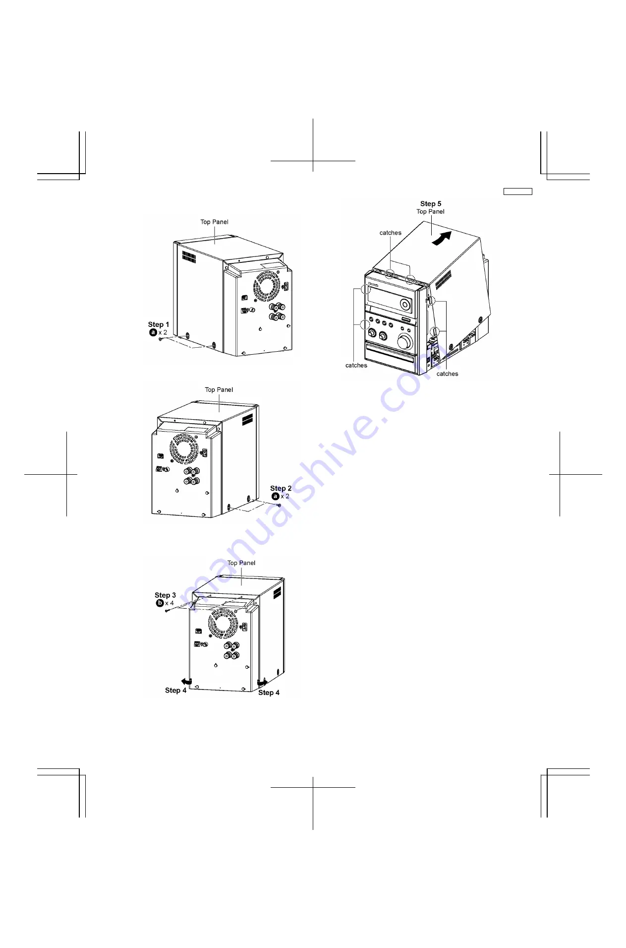
8.3. Disassembly of Top Panel
Step 1 :
Remove 2 screws at the side of Top Panel (L).
Step 2 :
Remove 2 screws at the side of Top Panel (R).
Step 3 :
Remove 4 screws at the rear of Top Panel.
Step 4 :
Lift both sides of Top Panel outwards in the direction
of arrow.
Step 5 :
Lift up the back part of the Top Panel and remove it in
the direction of arrow.
Note : During assembling of top panel, ensure it seats
properly.
21
SA-PMX3GN
Summary of Contents for SA-PMX3GN
Page 10: ...6 Operation Procedures 6 1 Main Unit Key Buttons Operation 10 SA PMX3GN ...
Page 11: ...6 2 Remote Control Key Buttons Operation 6 3 Disc Information 11 SA PMX3GN ...
Page 18: ...18 SA PMX3GN ...
Page 20: ...8 2 Main Parts Location Diagram 20 SA PMX3GN ...
Page 56: ...56 SA PMX3GN ...
Page 58: ...SA PMX3GN 58 ...
Page 64: ...SA PMX3GN 64 ...
Page 66: ...66 SA PMX3GN ...
Page 86: ...SA PMX3GN 86 ...
Page 91: ...20 Exploded Views 20 1 Cabinet Parts Location SA PMX3GN 91 ...
Page 92: ...20 2 Packaging SA PMX3GN 92 ...