


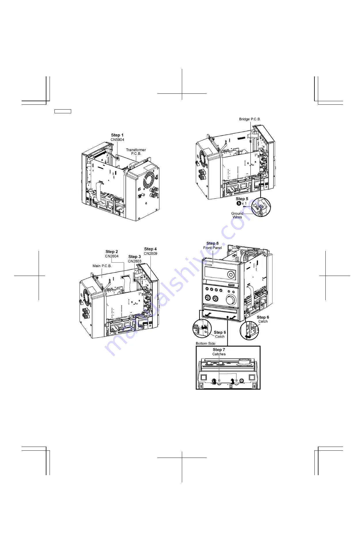
8.4. Disassembly of Front Panel
•
Follow the (Step 1) - (Step 5) of Item 8.3
Step 1 :
Detach 4P cable at the connector (CN5904) on
Transformer P.C.B..
Step 2 :
Detach 20P FFC cable at the connector (CN2804) on
Main P.C.B..
Step 3 :
Detach 17P FFC cable at the connector (CN2803) on
Main P.C.B..
Step 4 :
Detach 4P cable at the connector (CN2809) on Main
P.C.B..
Step 5 :
Remove 1 screw on Bridge P.C.B..
Caution :
Do not exert strong force when releasing the
catches.
Step 6 :
Release the catch at each side of the Front Panel in
the direction of arrow.
Step 7 :
Release the catches at the bottom of the Front Panel.
Step 8 :
Remove Front Panel.
22
SA-PMX3GN
Summary of Contents for SA-PMX3GN
Page 10: ...6 Operation Procedures 6 1 Main Unit Key Buttons Operation 10 SA PMX3GN ...
Page 11: ...6 2 Remote Control Key Buttons Operation 6 3 Disc Information 11 SA PMX3GN ...
Page 18: ...18 SA PMX3GN ...
Page 20: ...8 2 Main Parts Location Diagram 20 SA PMX3GN ...
Page 56: ...56 SA PMX3GN ...
Page 58: ...SA PMX3GN 58 ...
Page 64: ...SA PMX3GN 64 ...
Page 66: ...66 SA PMX3GN ...
Page 86: ...SA PMX3GN 86 ...
Page 91: ...20 Exploded Views 20 1 Cabinet Parts Location SA PMX3GN 91 ...
Page 92: ...20 2 Packaging SA PMX3GN 92 ...


