


Note: For description of the disassembly procedures, see
the Section 8
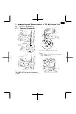
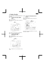
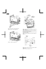
11.1. Checking & Repairing Main
P.C.B.
Step 1 :
Remove Top Panel.
Step 2 :
Remove Rear Panel and position it according to the
diagram show.
Step 3 :
Main P.C.B. can be checked at its original position.
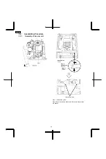
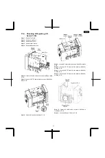
11.2. Checking & Repairing
Transformer P.C.B.
Step 1 :
Remove Top Panel.
Step 2 :
Remove Rear Panel and position it according to the
diagram show.
Step 3 :
Transformer P.C.B. can be checked at its original
position.
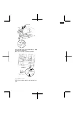
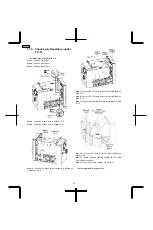
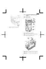
11.3. Checking & Repairing Panel A
P.C.B.
Step 1 :
Remove Top Panel.
Step 2 :
Remove Front Panel and position it according to the
diagram show.
Step 3 :
Attach extension cable REEX0922 (17P FFC cable
from CN6801 to CN2803).
11 Service Position
43
SA-PMX3GN
Summary of Contents for SA-PMX3GN
Page 10: ...6 Operation Procedures 6 1 Main Unit Key Buttons Operation 10 SA PMX3GN ...
Page 11: ...6 2 Remote Control Key Buttons Operation 6 3 Disc Information 11 SA PMX3GN ...
Page 18: ...18 SA PMX3GN ...
Page 20: ...8 2 Main Parts Location Diagram 20 SA PMX3GN ...
Page 56: ...56 SA PMX3GN ...
Page 58: ...SA PMX3GN 58 ...
Page 64: ...SA PMX3GN 64 ...
Page 66: ...66 SA PMX3GN ...
Page 86: ...SA PMX3GN 86 ...
Page 91: ...20 Exploded Views 20 1 Cabinet Parts Location SA PMX3GN 91 ...
Page 92: ...20 2 Packaging SA PMX3GN 92 ...