


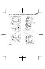
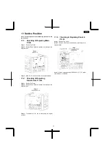


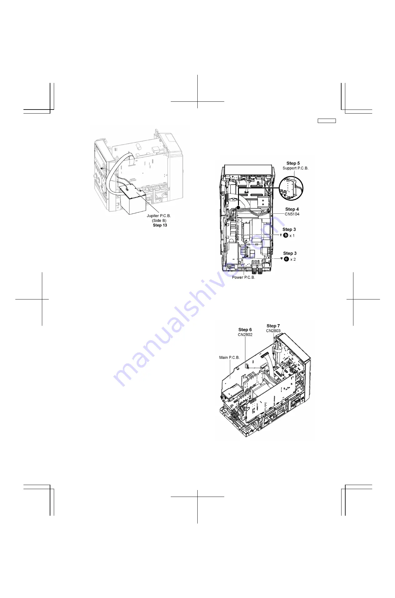
Step 13 :
Flip Jupiter P.C.B. to its Side B.
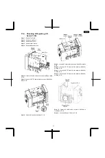
11.5. Checking & Repairing Power
P.C.B.
Step 1 :
Remove Top Panel.
Step 2 :
Remove Rear Panel.
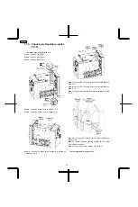
Step 3 :
Remove 3 screws on Power P.C.B..
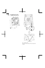
Step 4 :
Detach 8P cable at the connector (CN5104) on Power
P.C.B..
Step 5 :
Detach 8P cable from Support P.C.B..
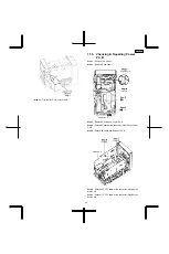
Step 6 :
Detach 22P FFC cable at the connector (CN2802) on
Main P.C.B..
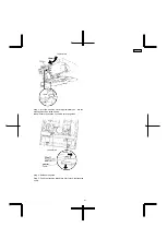
Step 7 :
Detach 17P FFC cable at the connector (CN2803) on
Main P.C.B..
45
SA-PMX3GN
Summary of Contents for SA-PMX3GN
Page 10: ...6 Operation Procedures 6 1 Main Unit Key Buttons Operation 10 SA PMX3GN ...
Page 11: ...6 2 Remote Control Key Buttons Operation 6 3 Disc Information 11 SA PMX3GN ...
Page 18: ...18 SA PMX3GN ...
Page 20: ...8 2 Main Parts Location Diagram 20 SA PMX3GN ...
Page 56: ...56 SA PMX3GN ...
Page 58: ...SA PMX3GN 58 ...
Page 64: ...SA PMX3GN 64 ...
Page 66: ...66 SA PMX3GN ...
Page 86: ...SA PMX3GN 86 ...
Page 91: ...20 Exploded Views 20 1 Cabinet Parts Location SA PMX3GN 91 ...
Page 92: ...20 2 Packaging SA PMX3GN 92 ...


