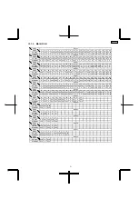
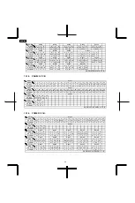
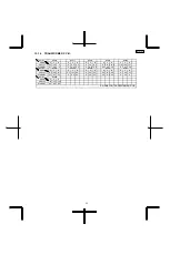


(All schematic diagrams may be modified at any time with
the development of new technology)
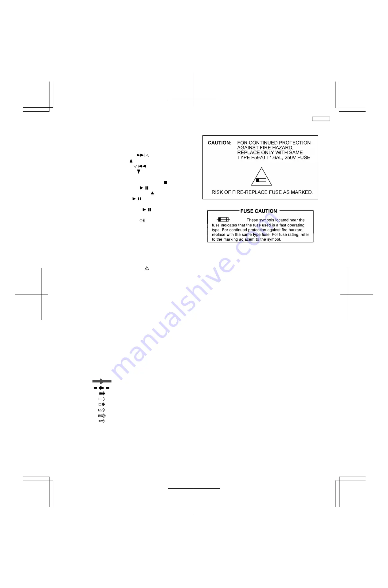
Notes:
S6801:
RIGHT (
/ ) switch.
S6802:
UP ( ) switch.
S6803:
LEFT ( /
) switch.
S6804:
DOWN ( ) switch.
S6805:
FM/AM/MUSIC P. switch.
S6806:
STOP/DEMO (-DEMO/
) switch.
S6807:
OPTION (
/
) switch.
S6808:
OPEN/CLOSE ( ) switch.
S6809:
USB (
/
) switch.
S6810:
D.BASS switch.
S6811:
CD_PLAY (
/
) switch.
S6812:
REC_USB switch.
S6813:
POWER (
) switch.
S7201:
REST switch.
S7202:
CD OPEN switch.
VR6801:
VR VOLUME jog.
VR6881:
VR BASS jog.
VR6882:
VR TREBLE jog.
•
Importance safety notice :
Components
identified
by
mark
have
special
characteristics important for safety.
Furthermore, special parts which have purposes of fire-
retardant (resistors), high-quality sound (capacitors), low-
noise (resistors), etc. are used.
When replacing any of components, be sure to use only
manufacturer´s specified parts shown in the parts list.
•
Resistor
Unit of resistance is OHM [
Ω
] (K=1,000).
•
Capacitor
Unit of resistance is µF, unless otherwise noted. F=Farad,
pF=Pico-Farad
•
Coil
Unit of inductance is H, unless otherwise noted.
•
*
For Indication only.
•
Voltage and Signal lines:
: +B Signal line
: -B Signal line
: CD-DA signal line
: CD signal line
: FM/AM signal line
: MAIN signal line
: MUSIC PORT / D-DOCK signal line
: USB signal line
15 Notes Of Schematic Diagram
65
SA-PMX3GN
Summary of Contents for SA-PMX3GN
Page 10: ...6 Operation Procedures 6 1 Main Unit Key Buttons Operation 10 SA PMX3GN ...
Page 11: ...6 2 Remote Control Key Buttons Operation 6 3 Disc Information 11 SA PMX3GN ...
Page 18: ...18 SA PMX3GN ...
Page 20: ...8 2 Main Parts Location Diagram 20 SA PMX3GN ...
Page 56: ...56 SA PMX3GN ...
Page 58: ...SA PMX3GN 58 ...
Page 64: ...SA PMX3GN 64 ...
Page 66: ...66 SA PMX3GN ...
Page 86: ...SA PMX3GN 86 ...
Page 91: ...20 Exploded Views 20 1 Cabinet Parts Location SA PMX3GN 91 ...
Page 92: ...20 2 Packaging SA PMX3GN 92 ...


