10.33. Disassembly of Drive Gear (A)
& Drive Gear (B)
·
Follow (Step 1) to (Step 3) of Item 10.3.
·
Follow (Step 1) to (Step 3) of Item 10.4.
·
Follow (Step 1) to (Step 4) of Item 10.5.
·
Follow (Step 1) to (Step 4) of Item 10.7.
·
Follow (Step 1) to (Step 4) of Item 10.8.
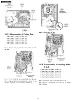
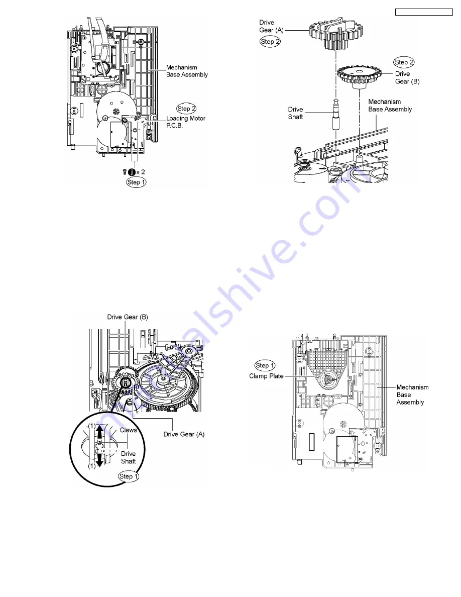
Step 1
Release the claws in the direction of arrow (1), and then
pull up the drive shaft.
Step 2
Remove the drive gear (A) and drive gear (B) from the
mechanism base assembly .
10.34. Disassembly of Magnet
Holder, Washer, Magnet &
Clamper
·
Follow (Step 1) to (Step 3) of Item 10.3.
·
Follow (Step 1) to (Step 3) of Item 10.4.
·
Follow (Step 1) to (Step 4) of Item 10.5.
·
Follow (Step 1) to (Step 4) of Item 10.7.
·
Follow (Step 1) to (Step 4) of Item 10.8.
·
Follow (Step 1) to (Step 3) of Item 10.30.
Step 1
Flip the mecha base to show the reverse side of the
clamp plate.
Step 2
Release 3 claws at the clamp plate in the direction of
arrow.
Step 3
Remove the magnet holder, washer, magnet & clamper.
69
SA-PT650P / SA-PT650PC
Summary of Contents for SA-PT650P
Page 12: ...12 SA PT650P SA PT650PC ...
Page 18: ...7 5 Using the Music Port 18 SA PT650P SA PT650PC ...
Page 54: ...10 2 Main Components and P C B Locations 54 SA PT650P SA PT650PC ...
Page 75: ...75 SA PT650P SA PT650PC ...
Page 90: ...SA PT650P SA PT650PC 90 ...
Page 98: ...SA PT650P SA PT650PC 98 ...
Page 100: ...100 SA PT650P SA PT650PC ...
Page 120: ...SA PT650P SA PT650PC 120 ...
Page 128: ...SA PT650P SA PT650PC 128 ...
Page 135: ...25 Exploded Views 135 SA PT650P SA PT650PC ...
Page 136: ...136 SA PT650P SA PT650PC ...
Page 137: ...25 1 Cabinet Parts Location SA PT650P SA PT650PC 137 ...
Page 138: ...SA PT650P SA PT650PC 138 ...


