8.2.2.2. TX-TYPE B / RX-TYPE 2
ADC
BB
RF
MCU
EEPRO
M
ADC
DAC
BB
RF
EEPRO
M
MCU
CH2
IN
CH1 IN
CH2
OUT
Note:
-
FX65/FX66 SIGNAL FLOW
-
FX85 S
SIGNAL F
FLOW
- ONE WAY AND
SIMULTANEOUS
- FX65/FX66 + FX85
-
FX65/FX66 TRANSMITTER NOT
USED, NEED TO IDSET
FX65/FX66
-
TX TYPE B BUT RX
CHANGED FROM TYPE 2
TO TYPE 1, CH1 SIGNAL
REDIRECTED TO DAC
TX Type B
RX Type 2
•
•
•
•
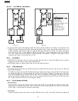
Type B transmitter uses two ADC (Analog to Digital Converter) to send audio streams from Channel 1 and Channel 2 for the
FX65/FX66 surround sound and FX85 second room audio, respectively. Type 2 receiver outputs audio through Channel 2. The
software multiplexes which channel to listen to by setting the baseband accordingly. For example, if the receiver is configured
as an FX85 receiver (Type 2), the baseband is configured to accept Channel 1 audio transmission and redirect it to Channel
2 Out. If the receiver is set as an FX65/FX66 or wireless subwoofer, the baseband is configured to accept channel 2 audio
transmission and redirect it to the same Channel 2 Out.
8.2.3. Activation
•
•
•
•
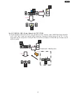
FX65/FX66 can be activated in the main unit by using either transmitter Type A or Type B and enabling surround sound by
selecting Surround Music, DPL or Super Surround (Music/Movie).
•
•
•
•
FX85 Wireless feature is enabled by default when the user uses transmitter type B.
8.2.4. LED Indication
•
•
•
•
For FX65/FX66, there will be two-color LED that will be used to indicate Power On and Link. If link, the two-color LED will be
green, else, it will be red.
For FX85, the front panel will have LED indicators for Standby,, Wireless Link, Charge, Option and Music Port. During Power
On, Standby LED will be OFF. Only during power OFF will this LED be ON (Red). Wireless Link indicator will be ON (Green)
when link is established between TX and RX and OFF when link is lost. Pressing the selector button will toggle from any of the
selector modes Wireless, Option and Music port. Only the currently selected mode will be ON (Green), the other two will be
OFF. Charge LED will be ON (Red) once iPod charging is initiated.
8.2.5. Key Operation (FX85)
•
•
•
•
Selector Button
This button will be used to select Wireless, Option or M.Port and enabling the corresponding LED indicators for each mode.
During Power On, by default, selector mode is set to Wireless when power is initially supplied to the system. But during Power
On/OFF button, it will remember the last selector mode setting.
•
•
•
•
Play Button
This button will send command to the main unit to play CD/DVD as well as the iPod. This function is therefore meaningful only
24
SA-PT750PL
Summary of Contents for SA-PT750PL
Page 11: ...11 SA PT750PL ...
Page 17: ...7 5 Using the Music Port 28 17 SA PT750PL ...
Page 21: ...8 1 3 Advanced Digital Sound 8 1 4 Easy to Use 8 1 5 HDMI Compatible Products 21 SA PT750PL ...
Page 50: ...10 2 Main Components and P C B Locations 50 SA PT750PL ...
Page 67: ...67 SA PT750PL ...
Page 84: ...SA PT750PL 84 ...
Page 86: ...SA PT750PL 84 ...
Page 94: ...SA PT750PL 92 ...
Page 96: ...94 SA PT750PL ...
Page 114: ...SA PT750PL 112 ...
Page 127: ...25 Exploded Views 125 SA PT750PL ...
Page 128: ...126 SA PT750PL ...
Page 129: ...25 1 Cabinet Parts Location SA PT750PL 127 ...
Page 130: ...SA PT750PL 128 ...
Page 131: ...25 2 Packaging SA PT750PL 129 ...

