12 Service Positions
12.1. Checking & Repair Panel
P.C.B. & Key P.C.B.
Step 1 Disassemble the top cabinet.
Step 2 Disassemble the tray lid assembly.
Step 3 Disassemble the front panel.
Step 4 Disassemble Panel & Key P.C.B.
Note: Refer to items in Chapter 10 for disassembly procedures
of respective Part & P.C.B.
Step 5 Connect FFC cable at the connector (CN7002) on Tray
P.C.B.
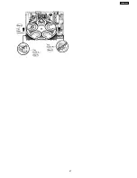
Step 6 Turn over Panel P.C.B. & Key P.C.B. horizontally and
place them according to the diagram shown below.
12.2. Checking & Repair Main P.C.B.
•
•
•
•
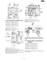
Disassembly of P.C.B. & Part
Step 1 Disassemble the top cabinet.
Step 2 Disassemble the tray lid assembly.
Step 3 Disassemble the front panel.
Step 4 Disassemble Panel & Key P.C.B.
Step 5 Disassemble the tray base assembly.
Step 6 Disassemble the mechanism base assembly.
Step 7 Disassemble the rear panel.
Step 8 Disassemble Wireless Adapter P.C.B.
Step 9 Disassemble Tray P.C.B.
Step 10 Disassemble D-Amp P.C.B.
Step 11 Disassemble DVD Module P.C.B.
Step 12 Disassemble Main P.C.B.
Step 13 Disassemble SMPS & AC-Inlet P.C.B.
Note: Refer to items in Chapter 10 for disassembly procedures
of respective Part & P.C.B.
•
•
•
•
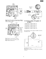
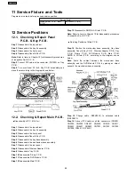
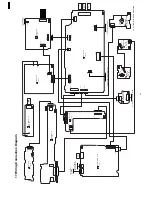
Servicing Position of Main P.C.B.
Step 14 Position the mechanism base assembly, tray base
assembly, Panel & Key P.C.B., Wireless Adapter P.C.B., Tray
P.C.B., D-Amp P.C.B., DVD Module P.C.B., Main P.C.B.,
SMPS & AC-Inlet P.C.B. according to the diagram shown
below.
Note: Avoid the contact between the mechanism base
assembly and the DVD Module P.C.B. by placing an object
beneath the mechanism base assembly.
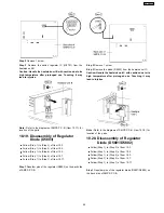
Step 15 Change cable (REEX0524) to extended cable
(REEX0633).
Step 16 Connect FFC cable at all the connectors. (CN2001,
CN2003, CN2005 CN2007, CN2009, CN2010, CN2011,
CN5501, CN5801, CN5802, CN7001, CN7002, CN7003,
CN7004, FP8251 & FP8531)
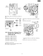
11 Service Fixture and Tools
Prepare service tools before proccess service position.
Service Tools
Loading Motor P.C.B. - Main
P.C.B.
REEX0633 (11 pin)
68
SA-PT750PL
Summary of Contents for SA-PT750PL
Page 11: ...11 SA PT750PL ...
Page 17: ...7 5 Using the Music Port 28 17 SA PT750PL ...
Page 21: ...8 1 3 Advanced Digital Sound 8 1 4 Easy to Use 8 1 5 HDMI Compatible Products 21 SA PT750PL ...
Page 50: ...10 2 Main Components and P C B Locations 50 SA PT750PL ...
Page 67: ...67 SA PT750PL ...
Page 84: ...SA PT750PL 84 ...
Page 86: ...SA PT750PL 84 ...
Page 94: ...SA PT750PL 92 ...
Page 96: ...94 SA PT750PL ...
Page 114: ...SA PT750PL 112 ...
Page 127: ...25 Exploded Views 125 SA PT750PL ...
Page 128: ...126 SA PT750PL ...
Page 129: ...25 1 Cabinet Parts Location SA PT750PL 127 ...
Page 130: ...SA PT750PL 128 ...
Page 131: ...25 2 Packaging SA PT750PL 129 ...


