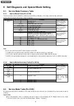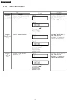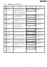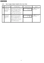
8.2.4. Service Mode Table 4
FL Display
Key Operation
Front Key
Item
Description
Mode Name
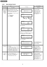
DVD
Module P.C.B.
firmware
version display
Cancelled automatically
5 seconds later.
In STOP (no disc)
mode, press [STOP]
button on the main unit,
and [8] button on the
remote control unit.
DVD Module P.C.B. firmware version is
displayed on the FL Display.
The firmware version can be updated
using recovery disc.
Note: It is necessary to check for
firmware version before carrying out
the version up using the disc.
Destination
System
controller
version
System controller
generation
Region No.: 0-8
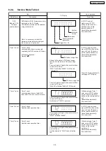
Timer 1 check
DVD laser usage time
(Display 1)
Shown to the above is DVD laser usage
time, and to the below is CD laser usage
time.
Time is shown in 5 digits of decimal notation
in a unit of 10 hours.
"00000" will follow "99999". (DVD laser)
(Display 2)
CD laser usage time
Time is shown in 6 digits of decimal notation
in a unit of 10 hours.
"000000" will follow "999999". (CD laser)
Press [FL Display] button for
next page of FL Display.
Cancelled automatically
5 seconds later.
In STOP (no disc) mode,
press [STOP] button on the
main unit, and [ ] button
on the remote control unit.
Timer 1 reset
Timer 2 check
Timer 2 reset
Timer 1 check
Laser operation timer is measured
separately for DVD laser and CD laser.
FL Display sequence:
Display 1 2.
Timer 1 reset
Laser operation timer of both DVD
laser and CD laser is reset all at once.
Timer 2 check
Spindle motor operation timer
Timer 2 reset
Spindle motor operation timer
Time is shown in 5 digits of decimal notation
in a unit of 10 hours.
It will clear to "00000" upon reset.
Time is shown in 5 digits of decimal notation in
a unit of 1 hour.
"00000" will follow "99999".
Time is shown in 5 digits of decimal notation in
a unit of 1 hour.
It will be cleared to "00000" upon activating
this.
Cancelled automatically
5 seconds later
While displaying Timer 1
data, press [STOP] button
on the main unit, and [ ]
button on the remote control
unit.
Cancelled automatically
5 seconds later.
In STOP (no disc) mode,
press [STOP] button on the
main unit, and [ ] button
on the remote control unit.
Cancelled automatically
5 seconds later.
While displaying Timer 2
data, press [STOP] button
on the main unit, and [ ]
button on the remote
control unit.
29
SA-PT960P / SA-PT960PC
Summary of Contents for SA-PT960P
Page 12: ...12 SA PT960P SA PT960PC ...
Page 44: ...44 SA PT960P SA PT960PC ...
Page 46: ...9 2 Main Components and P C B Locations 46 SA PT960P SA PT960PC ...
Page 80: ...14 Voltage and Waveform Chart 14 1 DVD Module P C B 80 SA PT960P SA PT960PC ...
Page 92: ...SA PT960P SA PT960PC 92 ...
Page 102: ...102 SA PT960P SA PT960PC ...
Page 130: ...CN5501 Fig 3 Fan Connector 130 SA PT960P SA PT960PC ...
Page 132: ...Table 1 132 SA PT960P SA PT960PC ...
Page 136: ...136 SA PT960P SA PT960PC ...
Page 141: ...24 Exploded Views 24 1 Cabinet Parts Location SA PT960P SA PT960PC 141 ...

