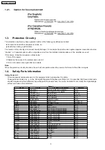
1.2.1. Caution for fuse replacement
1.3. Protection Circuitry
The protection circuitry may have operated if either of the following conditions are noticed:
•
•
•
•
No sound is heard when the power is turned on.
•
•
•
•
Sound stops during a performance.
The function of this circuitry is to prevent circuitry damage if, for example, the positive and negative speaker connection wires are
“shorted”, or if speaker systems with an impedance less than the indicated rated impedance of the amplifier are used.
If this occurs, follow the procedure outlines below:
1. Turn off the power.
2. Determine the cause of the problem and correct it.
3. Turn on the power once again after one minute.
Note:
When the protection circuitry functions, the unit will not operate unless the power is first turned off and then on again.
1.4. Safety Parts Information
Safety Parts List:
There are special components used in this equipment which are important for safety.
These parts are marked by
in the Schematic Diagrams & Replacement Parts List. It is essential that these critical parts
should be replaced with manufacturer’s specified parts to prevent shock, fire or other hazards. Do not modify the original design
without permission of manufacturer.
Table 1
Ref. No.
Part No.
Part Name & Description
Remarks
12
REXX0640-J
BLACK WIRE (AC TO SMPS)
[M]
13
REXX0641-J
RED WIRE (AC TO SMPS)
[M]
23
RGRX0067J-C2
REAR PANEL
[M] P
23
RGRX0067J-D2
REAR PANEL
[M] PC
66
RKMX0141-K
TOP CABINET
[M]
84
J0KD00000126
FERRITE CORE
[M]
PCB3
REPX0622A
SMPS P.C.B
[M] (RTL)
PCB4
REPX0622A
AC INLET P.C.B
[M] (RTL)
DZ5701
ERZV10V511CS
ZENER
[M]
L5702
G0B932H00001
LINE FILTER
[M]
T2900
G4D1A0000117
SWITCHING TRANSFORMER
[M]
T5701
ETS42BM18GAD
SWITCHING TRANSFORMER
[M]
T5751
ETS19AB256AG
SWITCHING TRANSFORMER
[M]
PC5701
B3PBA0000402
PHOTO COUPLER
[M]
PC5702
B3PBA0000402
PHOTO COUPLER
[M]
PC5720
B3PBA0000402
PHOTO COUPLER
[M]
PC5799
B3PBA0000402
PHOTO COUPLER
[M]
F1
K5D802APA008
FUSE
[M]
FP2901
K5G401A00008
FUSE PROTECTOR
[M]
TH5701
D4CAA5R10001
THERMISTOR
[M]
TH5860
D4CC11040013
THERMISTOR
[M]
P5701
K2AB2B000010
AC INLET
[M]
A2
K2CB2CB00021
AC CORD
[M]
C5700
F1BAF1020020
1000pF
[M]
C5701
F0CAF334A087
0.33uF
[M]
C5703
F0CAF224A085
0.22uF
[M]
6
SA-PT960P / SA-PT960PC
Summary of Contents for SA-PT960P
Page 12: ...12 SA PT960P SA PT960PC ...
Page 44: ...44 SA PT960P SA PT960PC ...
Page 46: ...9 2 Main Components and P C B Locations 46 SA PT960P SA PT960PC ...
Page 80: ...14 Voltage and Waveform Chart 14 1 DVD Module P C B 80 SA PT960P SA PT960PC ...
Page 92: ...SA PT960P SA PT960PC 92 ...
Page 102: ...102 SA PT960P SA PT960PC ...
Page 130: ...CN5501 Fig 3 Fan Connector 130 SA PT960P SA PT960PC ...
Page 132: ...Table 1 132 SA PT960P SA PT960PC ...
Page 136: ...136 SA PT960P SA PT960PC ...
Page 141: ...24 Exploded Views 24 1 Cabinet Parts Location SA PT960P SA PT960PC 141 ...


