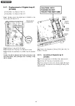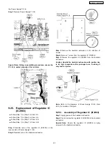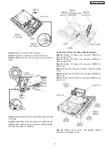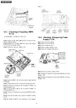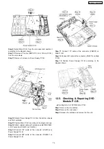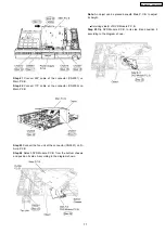
the Power Supply P.C.B.
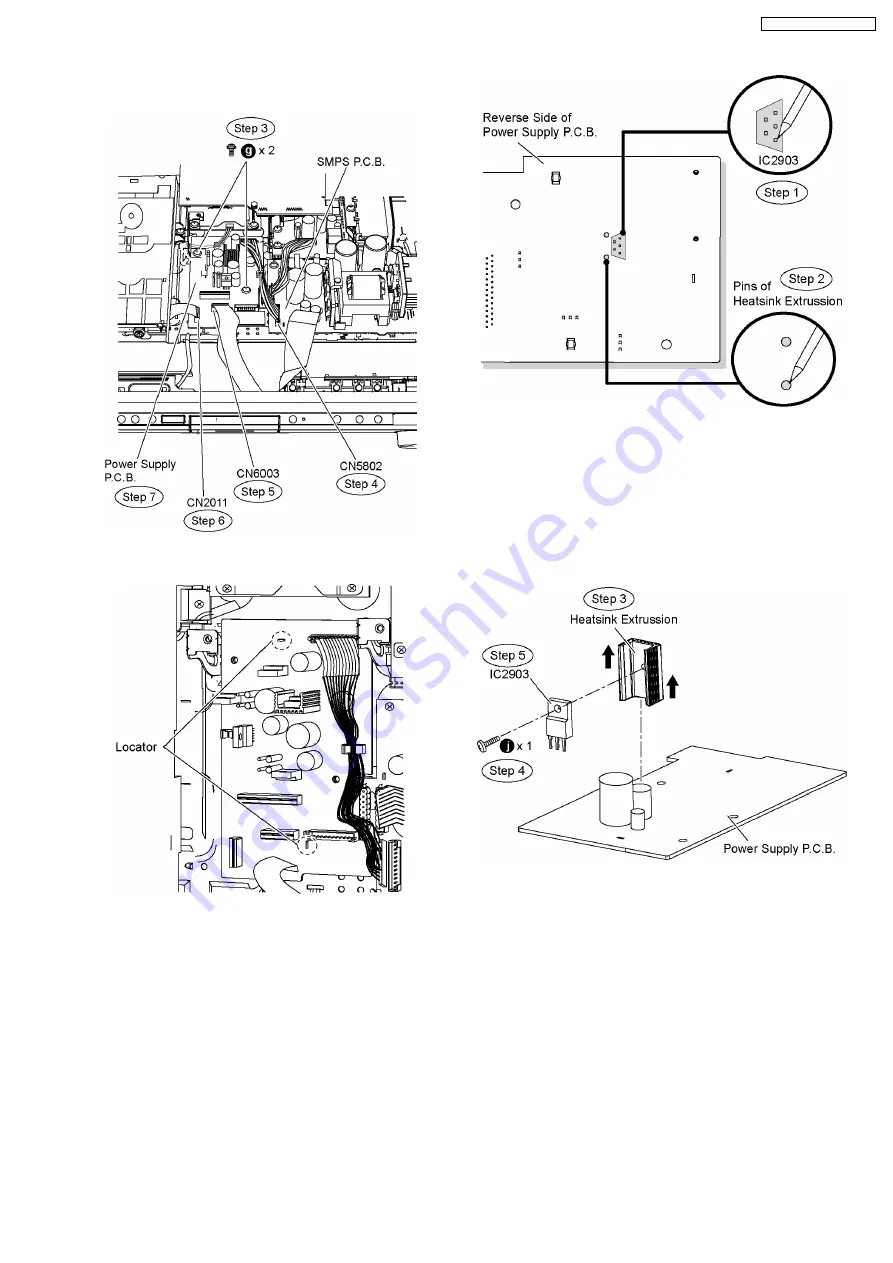
Step 7 Remove Power Supply P.C.B.
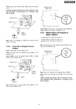
Special Note: During reassembling procedures, ensure the
P.C.B. is seated properly at the locators.
9.25. Replacement of Regulator IC
(IC2903)
•
•
•
•
Follow (Step 1) to (Step 3) of Item 9.3.
•
•
•
•
Follow (Step 1) to (Step 5) of Item 9.6.
•
•
•
•
Follow (Step 1) to (Step 7) of Item 9.12.
•
•
•
•
Follow (Step 1) to (Step 7) of Item 9.24.
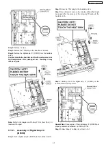
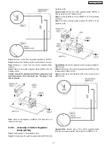
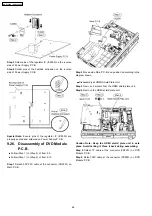
Step 1 Desolder pins of the regulator IC (IC2903) on the
reverse side of Power Supply P.C.B.
Step 2 Desolder pins of the heatsink extrussion.
Step 3 Remove the heatsink extrussion in the direction of
arrows.
Step 4 Remove 1 screw from the regulator IC (IC2903).
Step 5 Remove the regulator IC (IC2903) from the heatsink
extrussion.
Caution: Handle the heatsink extrussion with caution due
to its high temperature after prolonged use. Touching it
may lead to injuries.
Note: Refer to the diagrams of Power Supply P.C.B. (Item
20.3.) for location of the part.
9.25.1. Assembly of Regulator IC (IC2903)
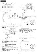
Step 1 Apply grease to the heatsink extrussion.
Step 2 Fix and screw the regulator IC (IC2903) to the heatsink
extrussion.
Special Note: Ensure the regulator IC (IC2903) is tighly
screwed to the heatsink extrussion.
65
SA-PT960P / SA-PT960PC
Summary of Contents for SA-PT960P
Page 12: ...12 SA PT960P SA PT960PC ...
Page 44: ...44 SA PT960P SA PT960PC ...
Page 46: ...9 2 Main Components and P C B Locations 46 SA PT960P SA PT960PC ...
Page 80: ...14 Voltage and Waveform Chart 14 1 DVD Module P C B 80 SA PT960P SA PT960PC ...
Page 92: ...SA PT960P SA PT960PC 92 ...
Page 102: ...102 SA PT960P SA PT960PC ...
Page 130: ...CN5501 Fig 3 Fan Connector 130 SA PT960P SA PT960PC ...
Page 132: ...Table 1 132 SA PT960P SA PT960PC ...
Page 136: ...136 SA PT960P SA PT960PC ...
Page 141: ...24 Exploded Views 24 1 Cabinet Parts Location SA PT960P SA PT960PC 141 ...

