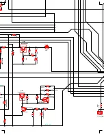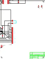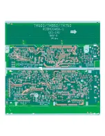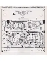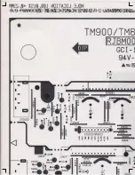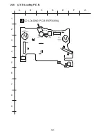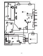
21.9. (I) Transformer Circuit
1
2
3
4
5
6
14
12
10
8
7
9
11
13
15
1
2
3
4
5
6
7
1
2
3
4
1
2
3
4
7
5
1
3
6
4
2
17
16
15
14
13
12
11
10
9
8
4
3
2
1
A: 220-240V
B: 110-127V
2
4
6
5
3
1
A
B
A
B
: -B SIGNAL LINE
: +B SIGNAL LINE
3
2
1
1
2
5
3
4
R9517
22K
R9836
4.7
C9501
0.1
R9515
1K
D9501
B0AACK000004
C9533
6.3V1
R9512
3.9K
R9513
470
L9500
G0ZZ00001930
R9514
1K
D9502
B0BA7R000005
R9511
10K
C9507
100P
C9514
25V1000P
D9503
B0JAPG000019
C9500
0.1
R9508
1
R9509
1
R9510
1
R9522
1
R9507
1
R9516
1K
R9502
10
R9501
10
R9500
10
D9508
B0EAKM000125
C9513 25V4700
D9527
D9526
D9525
D9523
D9524
D9522
D9529
D9528
C9506
0.01
FP9501
4000
F2
250V 2A
FC4
FC3
T9500
G4C8AGK00002
C9517
50V10
D9516
B0BA03100002
C9505
0.01
R9519
150
R9520
4.7K
R9521
4.7
C9512
50V47
D9514
D9513
D9513, D9514
B0EAKM000126
C9509
50V47
D9522 - D9529
B0EAKM000126
RL9500
K6B1AE00015
T9501
G4C2AAJ00005
D9500
B0AACK000004
C9504
0.01
R9518
3.3K
D9512
B0EAKM000125
D9517
B0EAKM000125
C9510
25V470
C9511
25V470
D9509
B0EAKM000125
R9504
1.5K
R9505
1.2K
C9503
1000P
R9503
820K
D9510
B0AACK000004
D9511
B0EAKM000125
C9502
0.01
D9515
B0BA7R000005
F1
250V 4A
FC2
FC1
Z9500
ERZV10V511CS
TO
POWER
CIRCUIT
(H9500) ON
SCHEMATIC
DIAGRAM - 23
FL_GND
FL2
FL1
PCONT
SYS6V
SYNC
-VP
DGND
DVD_PCONT
DVD_AC
D+5V
DGND
SUB+B
-VccH
-VccH
-VccL
AC_GND
AC_GND
+VccL
+VccH
+VccH
AC_IN
D9518 - D9521
B0EAKM000038
TRANSFORMER CIRCUIT
SCHEMATIC DIAGRAM - 25
CN5804
CN9500
TO
PANEL CIRCUIT
(H6800) ON
SCHEMATIC
DIAGRAM - 20
C5816
25V2200
C5817
25V2200
D9519
D9518
D9521
D9520
JK9500
S5950
VOLTAGE SELECTOR
D9504
B0FBAM000009
D9505
B0FBAM000009
Vsoft
0adj
COM
V
out
Vi
n
IC9500
C0DAAZG00012
DC - DC CONVERTER
Q9504
Q9503
2SB0621AHA
-VP REGULATOR
Q9502
B1AAGC000007
REGULATOR
Q9501
2SD21370PA
REGULATOR
Q9500
B1AAGC000007
PCONT SWITCH
Q9504
B1ACKD000004
POWER SUPPLY SWITCH
AC IN
110-127V/
220-240V
50/60Hz
FP9500
1000
C9508
10V47
FP9502
4000
FP9503
4000
SUB+BGND
D+5V
H9502/
W9502
TO
MAIN CIRCUIT
(CN2814) ON
SCHEMATIC
DIAGRAM - 12
K9801
K9802
K9801, K9802
ERDS2TJ1R0T
C9515
6.3V1000
5
4
3
2
1
118
Summary of Contents for SA-TM900DVD
Page 9: ...10 Operation Procedures 9 ...
Page 10: ...10 ...
Page 11: ...11 Disc information 11 ...
Page 12: ...12 ...
Page 15: ...15 ...
Page 35: ...Step 2 Remove DVD traverse deck by rotating to the arrow direction 35 ...
Page 39: ...39 ...
Page 40: ...16 17 3 Replacement for the traverse deck Follow the Step 1 Step 10 of item 16 17 2 40 ...
Page 42: ...42 ...
Page 43: ...43 ...
Page 45: ...45 ...
Page 46: ...46 ...
Page 47: ...47 ...
Page 48: ...48 ...
Page 49: ...49 ...
Page 50: ...50 ...
Page 51: ...51 ...
Page 52: ...52 ...
Page 53: ...53 ...
Page 54: ...54 ...
Page 55: ...55 ...
Page 65: ...18 3 1 Cassette Deck Section 18 3 2 Adjustment Point 18 3 Alignment Points 65 ...
Page 77: ...20 Voltage Measurement This section is not available at time of issue 77 ...
Page 107: ...35 6 6 7 7 7 7 7 7 6 U 2 2 2 0 2 1 2 2 1 2 2 1 2 1 2 2 2 4 6 35 ...
Page 109: ...0 7 7 7 2 2 2 3 4 6 EW ODEL GT IC OTE ATERIAL 3IZE MODIFIED 0 4 25 ...
Page 110: ...2 0 7 2 0 5NIT MM 0ARTS NO AME PPROVED HECKED 3 ...
Page 111: ......
Page 112: ......
Page 113: ......
Page 114: ......
Page 115: ......
Page 116: ...116 ...
Page 117: ...117 ...
Page 139: ...26 1 Deck Mechanism RAA3413 S 26 1 1 Deck Mechanism Parts Location 139 ...
Page 140: ...140 ...
Page 142: ...26 2 DVD Loading Mechanism 26 2 1 DVD Loading Mechanism Parts Location 142 ...
Page 143: ...143 ...
Page 145: ...26 3 Cabinet 26 3 1 Cabinet Parts Location 145 ...
Page 146: ...146 ...
Page 147: ...147 ...
Page 188: ...3 Connection of the Wiring Diagram 4 Cabinet Parts Location 5 service m speaker 11 ...
Page 192: ...3 Connection of the Wiring Diagram 9 service m speaker ...
Page 193: ...4 Cabinet Parts Location 3 10 service m speaker ...
Page 198: ...3 Connection of the Wiring Diagram 4 Cabinet Parts Location 15 service m speaker ...
Page 203: ...3 Connection of the Wiring Diagram 4 Cabinet Parts Location 20 service m speaker ...


