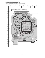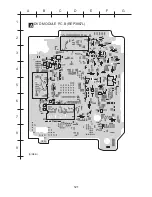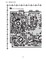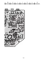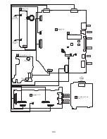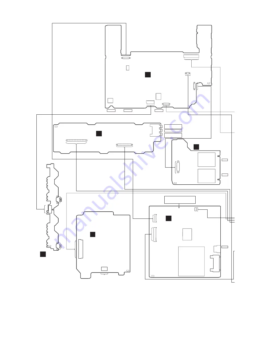
23 Wiring Connection Diagram
2 . . . . . . . . . . 30
1 . . . . . . . . . . 29
1 . . . . 9
2 . . . . 10
JK6801
CP6800
H6807
H6810
CN6811
VR6800
Z6800
1. . . . .7
1. . . . 6
2 1
H6800
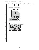
PHONES
SENSOR
VOLUME
C
PANEL P.C.B.
SOLDER SIDE
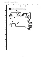
SOLENOID
SOLENOID
CN971
10
.
.
2
9
.
.
1
DECK
MECHANISM
P.C.B.
SOLDER SIDE
F
TRANSFORMER
P.C.B.
SOLDER SIDE
I
AC IN ~
110-127V/
220-240V
50/60HZ
CAUTION
RISK OF ELECTRIC SHOCK
AC VOLTAGE LINE. PLEASE DO NOT
TOUCH THIS P.C.B
T9501
(SUB-TRANSFORMER)
T9500
(POWER TRANSFORMER)
JK9500
S5950
7
CN9500
CN5804
1. . . . .
PbF
A
DVD MODULE P.C.B.
(SIDE A)
PbF
PbF
PbF
FP8101
1
50
. . . . . . . . . . . . . . . . .
FP8201
6 . . . .1
TO
SPINDLE
MOTOR
MIC P.C.B.
SOLDER SIDE
D
MIC 2
MIC 1
H6805
JK6800
JK6802
5
1
. . .
PbF
PbF
H6806
5
1
. . .
H5804
11 . . . . . . . . . 1
H5803
10 . . . . . . . 1
JK9502
RIGHT SURROUND
SPEAKER
CENTER SPEAKER
LEFT SURROUND
SPEAKER
15
1
. . . . .. . . . . . . .
3
H9502/
W9502
1.
SOLDER SIDE
H
POWER AMP P.C.B.
132
Summary of Contents for SA-TM900DVD
Page 9: ...10 Operation Procedures 9 ...
Page 10: ...10 ...
Page 11: ...11 Disc information 11 ...
Page 12: ...12 ...
Page 15: ...15 ...
Page 35: ...Step 2 Remove DVD traverse deck by rotating to the arrow direction 35 ...
Page 39: ...39 ...
Page 40: ...16 17 3 Replacement for the traverse deck Follow the Step 1 Step 10 of item 16 17 2 40 ...
Page 42: ...42 ...
Page 43: ...43 ...
Page 45: ...45 ...
Page 46: ...46 ...
Page 47: ...47 ...
Page 48: ...48 ...
Page 49: ...49 ...
Page 50: ...50 ...
Page 51: ...51 ...
Page 52: ...52 ...
Page 53: ...53 ...
Page 54: ...54 ...
Page 55: ...55 ...
Page 65: ...18 3 1 Cassette Deck Section 18 3 2 Adjustment Point 18 3 Alignment Points 65 ...
Page 77: ...20 Voltage Measurement This section is not available at time of issue 77 ...
Page 107: ...35 6 6 7 7 7 7 7 7 6 U 2 2 2 0 2 1 2 2 1 2 2 1 2 1 2 2 2 4 6 35 ...
Page 109: ...0 7 7 7 2 2 2 3 4 6 EW ODEL GT IC OTE ATERIAL 3IZE MODIFIED 0 4 25 ...
Page 110: ...2 0 7 2 0 5NIT MM 0ARTS NO AME PPROVED HECKED 3 ...
Page 111: ......
Page 112: ......
Page 113: ......
Page 114: ......
Page 115: ......
Page 116: ...116 ...
Page 117: ...117 ...
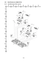
Page 139: ...26 1 Deck Mechanism RAA3413 S 26 1 1 Deck Mechanism Parts Location 139 ...
Page 140: ...140 ...
Page 142: ...26 2 DVD Loading Mechanism 26 2 1 DVD Loading Mechanism Parts Location 142 ...
Page 143: ...143 ...
Page 145: ...26 3 Cabinet 26 3 1 Cabinet Parts Location 145 ...
Page 146: ...146 ...
Page 147: ...147 ...
Page 188: ...3 Connection of the Wiring Diagram 4 Cabinet Parts Location 5 service m speaker 11 ...
Page 192: ...3 Connection of the Wiring Diagram 9 service m speaker ...
Page 193: ...4 Cabinet Parts Location 3 10 service m speaker ...
Page 198: ...3 Connection of the Wiring Diagram 4 Cabinet Parts Location 15 service m speaker ...
Page 203: ...3 Connection of the Wiring Diagram 4 Cabinet Parts Location 20 service m speaker ...


