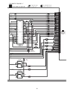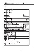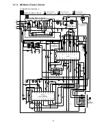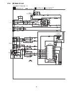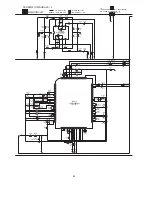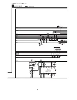
16
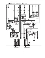
17
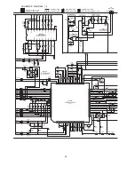
18
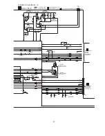
19
20
21
29
27
25
23
22
24
26
28
30
1
2
3
4
5
6
14
12
10
8
7
9
11
13
15
1
2
3
4
5
6
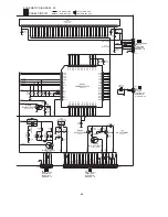
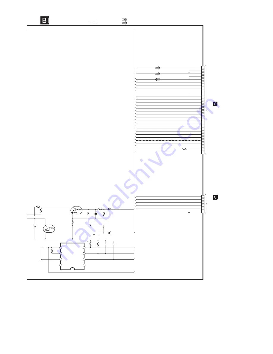
SW5V
PCONT
SYNC
DCDET
SYS6V
+9.0V
-9.0V
HPOUT_FR
HPGND
MICGND
MIC
HPOUT_FL
FLD_RST
FLD_CS
FLD_DA
FLD_CK
RMT
DGND
KEY1
HP_MUTE
JOG_B
PHOTO_1
KEY3
GND2
KEY2
JOG_A
DVREF+
DECK2
MOT10V
VREF+
PLUNGER2
MODE_1
HALF_1
PHOTO_2
PLUNGER1
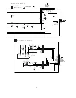
RMT
FLD_CS
FLD_RST
FLD_CK
FLD_DA
LEDCONT
LEDCONT
SYNC
MIC
KEY1
DCDET
-9.0V
+9.0V
SW5V
PCONT
SYS6V
HPOUT_FL
HPOUT_FR
MOT10V
VREF+
DVREF+
DECK2
HALF_1
MODE_1
PLUNGER2
PLUNGER1
PHOTO_2
PHOTO_1
HP_MUTE
JOG_B
JOG_A
KEY3
KEY2
ED_A
E_CLK
E_CS
VREF+
VREF+
SYNC
DATA
CLK
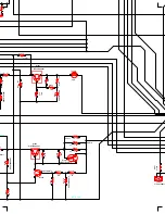
R2999 0
D2905
B0ACCK000005
Q2702
B1GBCFJJ0051
SWITCH
R2072
0
C2732
0.01
R2922
22K
R2920
10K
IC2816
C3EBEG000072
EEPROM IC
(NOT SUPPLIED)
C2733
50V2.2
R2913
10K
C2738
0.022
R2667
22K
Q2710
B1GBCFJJ0051
SYNC SWITCH
C2739
330P
D2906
B0ACCK000005
R2914
4.7K
C2741
35V4.7
CN2811
C2740
330P
R2923
2.2K
R2670
22K
C2731
50V0.1
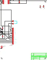
MAIN CIRCUIT
SCHEMATIC DIAGRAM - 18
CN2808
TO
PANEL CIRCUIT
(CN6811) ON
SCHEMATIC
DIAGRAM - 20
TO
PANEL CIRCUIT
(H6807) ON
SCHEMATIC
DIAGRAM - 20
: -B SIGNAL LINE
: +B SIGNAL LINE
: MAIN SIGNAL LINE
: MIC SIGNAL LINE
C2754
0.01
1
2
7
8
3
6
4
5
96
Summary of Contents for SA-TM900DVD
Page 9: ...10 Operation Procedures 9 ...
Page 10: ...10 ...
Page 11: ...11 Disc information 11 ...
Page 12: ...12 ...
Page 15: ...15 ...
Page 35: ...Step 2 Remove DVD traverse deck by rotating to the arrow direction 35 ...
Page 39: ...39 ...
Page 40: ...16 17 3 Replacement for the traverse deck Follow the Step 1 Step 10 of item 16 17 2 40 ...
Page 42: ...42 ...
Page 43: ...43 ...
Page 45: ...45 ...
Page 46: ...46 ...
Page 47: ...47 ...
Page 48: ...48 ...
Page 49: ...49 ...
Page 50: ...50 ...
Page 51: ...51 ...
Page 52: ...52 ...
Page 53: ...53 ...
Page 54: ...54 ...
Page 55: ...55 ...
Page 65: ...18 3 1 Cassette Deck Section 18 3 2 Adjustment Point 18 3 Alignment Points 65 ...
Page 77: ...20 Voltage Measurement This section is not available at time of issue 77 ...
Page 107: ...35 6 6 7 7 7 7 7 7 6 U 2 2 2 0 2 1 2 2 1 2 2 1 2 1 2 2 2 4 6 35 ...
Page 109: ...0 7 7 7 2 2 2 3 4 6 EW ODEL GT IC OTE ATERIAL 3IZE MODIFIED 0 4 25 ...
Page 110: ...2 0 7 2 0 5NIT MM 0ARTS NO AME PPROVED HECKED 3 ...
Page 111: ......
Page 112: ......
Page 113: ......
Page 114: ......
Page 115: ......
Page 116: ...116 ...
Page 117: ...117 ...
Page 139: ...26 1 Deck Mechanism RAA3413 S 26 1 1 Deck Mechanism Parts Location 139 ...
Page 140: ...140 ...
Page 142: ...26 2 DVD Loading Mechanism 26 2 1 DVD Loading Mechanism Parts Location 142 ...
Page 143: ...143 ...
Page 145: ...26 3 Cabinet 26 3 1 Cabinet Parts Location 145 ...
Page 146: ...146 ...
Page 147: ...147 ...
Page 188: ...3 Connection of the Wiring Diagram 4 Cabinet Parts Location 5 service m speaker 11 ...
Page 192: ...3 Connection of the Wiring Diagram 9 service m speaker ...
Page 193: ...4 Cabinet Parts Location 3 10 service m speaker ...
Page 198: ...3 Connection of the Wiring Diagram 4 Cabinet Parts Location 15 service m speaker ...
Page 203: ...3 Connection of the Wiring Diagram 4 Cabinet Parts Location 20 service m speaker ...

