Note: For description of the disassembly procedures, see
the Section 9.
12.1. Checking and Repairing of
Main P.C.B.
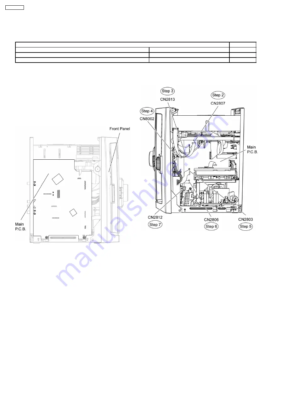
Step 1 Remove the top cabinet.
Note: Main P.C.B. can be checked at its original position.
12.2. Checking and Repairing Panel
P.C.B., Deck P.C.B., Tact
Switch P.C.B., Music Port
P.C.B. and Mic P.C.B.
Step 1 Remove the top cabinet.
Step 2 Detach 27P FFC cable at connector (CN2807) on Main
P.C.B..
Step 3 Detach 2P cable at connector (CN2813) on Main
P.C.B..
Step 4 Detach 5P cable at connector (CN8002) on USB
P.C.B..
Step 5 Detach 21P FFC cable at connector (CN2803) on Main
P.C.B..
Step 6 Detach 10P FFC cable at connector (CN2806) on Main
P.C.B..
Step 7 Detach 2P cable at connector (CN2812) on Main
P.C.B..
Step 8 Release the claws outwards on both sides.
Step 9 Release the catches at both sides.
11 Service Fixture and Tools
Prepare service tools before process service position.
Service Tools
Remarks
Main P.C.B. (CN2808) - D-AMP P.C.B. (CN5050)
REXX0930 (17P cable)
[M](RTL)
Main P.C.B. (CN2701) - SMPS P.C.B. (CN5802)
REEX0680 (11P cable)
[M](RTL)
SMPS P.C.B. (H5801) - D-Amp P.C.B. (CN5500)
REXX0683 (8P cable)
[M](RTL)
12 Service Positions
70
SA-VK470EE
Summary of Contents for SA-VK470EE
Page 3: ...3 SA VK470EE ...
Page 12: ...12 SA VK470EE ...
Page 40: ...40 SA VK470EE ...
Page 42: ...9 3 Main Components and P C B Location 42 SA VK470EE ...
Page 54: ...9 15 2 Replacement of Motor Capstan Belt A Capstan Belt B and Winding Belt 54 SA VK470EE ...
Page 88: ...SA VK470EE 88 ...
Page 98: ...98 SA VK470EE ...
Page 116: ...SA VK470EE 116 ...
Page 124: ...SA VK470EE 124 ...
Page 136: ...136 SA VK470EE ...
Page 137: ...24 Exploded Views 24 1 Cabinet Parts Location SA VK470EE 137 ...
Page 138: ...SA VK470EE 138 ...
Page 139: ...24 2 Deck Mechanism Parts Location RAA4111 S SA VK470EE 139 ...
Page 140: ...24 3 Packaging SA VK470EE 140 ...

