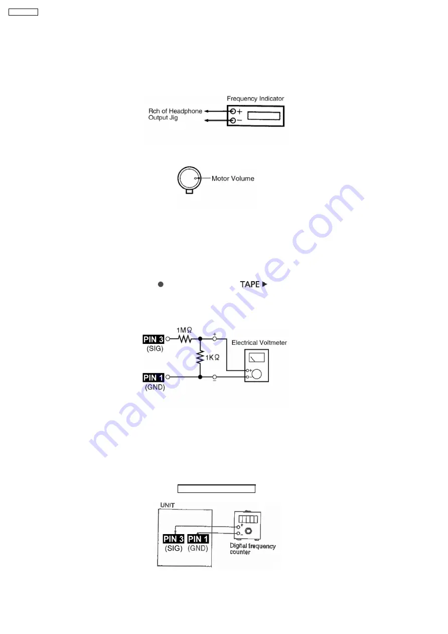
(Product reference value: 3,000±90Hz)
1. Connect a frequency indicator. (Fig 10)
2. Playback the middle portion of the test tape (QZZCWAT).
3. Adjust the motor screw so that the following output level is produced. (Fig 11)
Adjustment Range: 3,000 ± 90Hz (a constant speed)
Fig. 10
Fig. 11
14.1.5. Bias Voltage Check
1. Connect an electrical voltmeter. (Fig 12) (Fig 9 for location of Test point)
2. Set the function to “TAPE” position.
3. Insert a normal blank cassette tape (QZZCRA).
4. While pressing and holding down [REC(
)] button, press [TAPE(
)] button to pause the recording mode. (Repeat
pressing the buttons till the recording pause mode is activated.)
5. Check that the output level is within the standard range.
Standard Range: 14 ± 4mV
Fig. 12
14.1.6. Bias Frequency Check
1. Connect a digital frequency counter (Fig 13).
2. Set the function to “TAPE” position.
3. Insert a normal blank cassette tape (QZZCRA) and press “REC” mode on main unit.
4. Check that the output frequency is within the standard range.
Standard Value: 100 ±8 kHz
Fig. 13
78
SA-VK470EE
Summary of Contents for SA-VK470EE
Page 3: ...3 SA VK470EE ...
Page 12: ...12 SA VK470EE ...
Page 40: ...40 SA VK470EE ...
Page 42: ...9 3 Main Components and P C B Location 42 SA VK470EE ...
Page 54: ...9 15 2 Replacement of Motor Capstan Belt A Capstan Belt B and Winding Belt 54 SA VK470EE ...
Page 88: ...SA VK470EE 88 ...
Page 98: ...98 SA VK470EE ...
Page 116: ...SA VK470EE 116 ...
Page 124: ...SA VK470EE 124 ...
Page 136: ...136 SA VK470EE ...
Page 137: ...24 Exploded Views 24 1 Cabinet Parts Location SA VK470EE 137 ...
Page 138: ...SA VK470EE 138 ...
Page 139: ...24 2 Deck Mechanism Parts Location RAA4111 S SA VK470EE 139 ...
Page 140: ...24 3 Packaging SA VK470EE 140 ...

