22
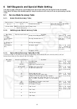
6 Self-Diagnosis and Special Mode Setting
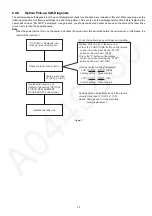
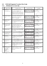
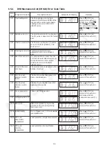
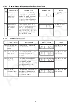
This unit is equipped with features od self-diagnosis & special mode setting for checking the function & reliability.
Special Note: Checking of the reliability (ageing) & changer operation must be carry out to ensure good working condition
in unit.
6.1.
Service Mode Summary Table
6.1.1.
Doctor Mode Summary Table
6.1.2.
Self-Diagnosis Mode Summary Table
6.1.3.
Service Mode Summary Table (For DVD)
The service modes can be activated by pressing various button combination on the main unit and remote control unit.
Below is the summary for the various modes for checking:
Main unit buttons
Remote control unit buttons
Application
Note
[
]
[4], [7]
Enter into doctor mode.
(Refer to the section “6.2. Doctor Mode
Table” for more information.)
(In Doctor Mode)
[
O
DISC] or [0133] (For Special
Remote Control only)
Changer check
Main buttons
Remote control unit buttons
Application
Note
[STOP] +
[ /FF/
]
-
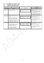
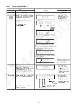
Entering into self-diagnostic mode.
(Refer to the section
“6.3.1. Self-Diagnosis
Mode Table 1” for more
information.)
(In self-diagnostic
mode) + [
]
-
Servicing the mechanism unit.
(In self-diagnostic
mode) + [
]
-
Servicing the traverse unit.
In Self-diagnosis
mode
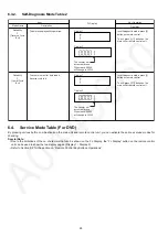
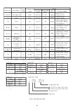
[2]
Reliability
2
(Cycle)
(Refer to the section
“6.3.2. Self-Diagnosis
Mode Table 2” for more
information.)
[3]
Reliability 3 (Combi)
Main buttons
Remote control unit buttons
Application
Note
[STOP]
[0]
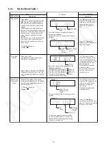
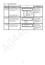
Error
code
display.
(Refer to the section
“6.4.1. Service Mode
Table 1” for more informa-
tion.)
[5]
Jitter checking.
[PAUSE]
Initial setting of laser drive current.
[FUNCTIONS]
DVD laser drive current check.
(Refer to the section
“6.4.2. Service Mode
Table 2” for more informa-
tion.)
[3]
CD laser drive current check.
[6]
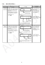
Region display and mode.
(Refer to the section
“6.4.3. Service Mode
Table 3“ for more informa-
tion.)
[7]
Micro-processor firmware version check.
Initialization of the player (factory setting is restored).
Used after replacement of Micro-processor (DV5 LSI) IC, FLASH
ROM IC (IC8651), EEPROM IC (IC8611) and DVD Module
P.C.B.
[8]
DVD Module P.C.B. firmware version check.
(Refer to the section
“6.4.4. Service Mode
Table 4“ for more informa-
tion.)
[DISC]
CPPM/CPRM keys check.
[ENTER]
DVD Module P.C.B. reset.
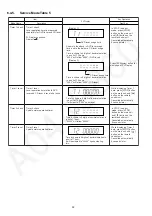
Timer
1
check.
(Refer to the section
“6.4.5. Service Mode
Table 5“ for more informa-
tion.)
Timer 1 reset.
Timer 2 check.
Timer 2 reset.
Summary of Contents for SA-VK680EE
Page 13: ...13 ...
Page 48: ...48 ...
Page 50: ...50 9 2 Main Components and P C B Location ...
Page 116: ...116 ...
Page 118: ...118 ...
Page 144: ...144 ...


