

85
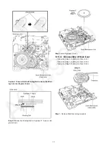
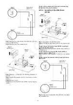
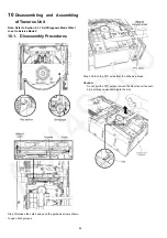
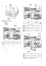
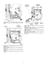
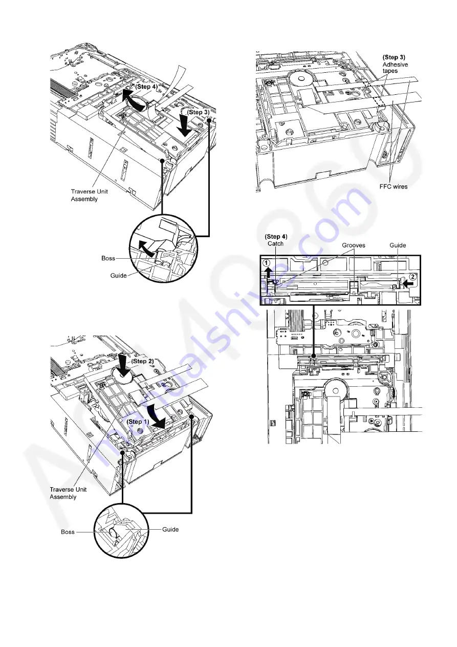
Step 3 Press down the traverse unit assembly.
Step 4 Remove the traverse unit assembly as arrow shown.
10.2. Assembly Procedures
Step 1 Slot the traverse unit assembly into the guides as arrow
shown.
Note: Ensure the bosses fix exactly onto the guides.
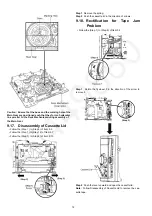
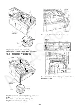
Step 2 Place down the traverse unit assy.
Step 3 Fix the FFC wires by using the adhesive tapes.
Step 4 Release the catch and push the guide as arrows shown
to close both grooves.
Summary of Contents for SA-VK680EE
Page 13: ...13 ...
Page 48: ...48 ...
Page 50: ...50 9 2 Main Components and P C B Location ...
Page 116: ...116 ...
Page 118: ...118 ...
Page 144: ...144 ...


