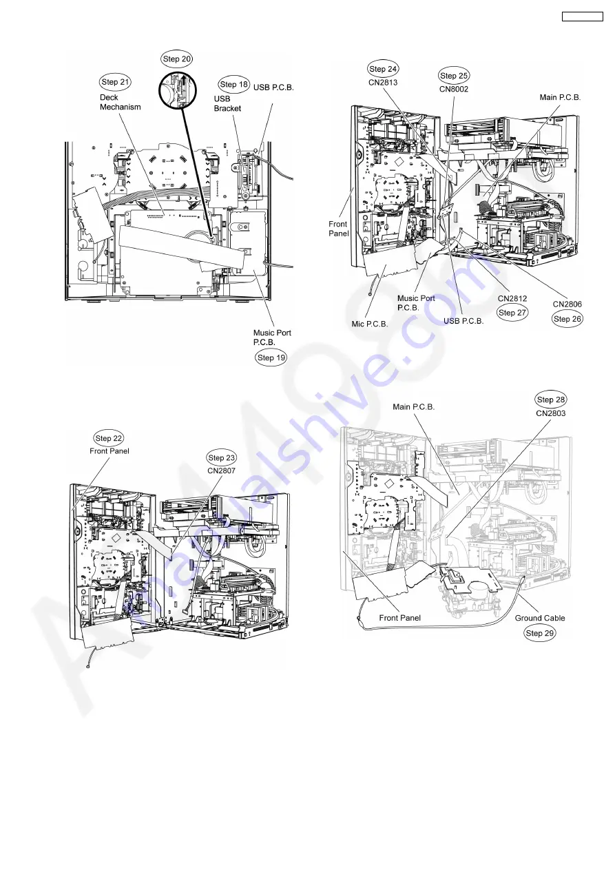
Step 22 Position front panel unit according to the diagram
show.
Step 23 Connect 27P FFC cable at connector (CN2807) on
Main P.C.B..
Step 24 Connect 2P cable at connector (CN2813) on Main
P.C.B..
Step 25 Connect 5P cable at connector (CN8002) on USB
P.C.B..
Step 26 Connect 10P FFC cable at connector (CN2806) on
Main P.C.B..
Step 27 Connect 2P cable at connector (CN2812) on Main
P.C.B..
Step 28 Connect 21P FFC cable at the connector (CN2803) on
Main P.C.B..
Step 29 Attach original grounding wire with ground cable.
Step 30 Check and repair panel P.C.B., Deck P.C.B., Tact
Switch P.C.B., Music Port P.C.B. and Mic P.C.B..
12.3. Checking and Repairing of D-
Amp P.C.B.
Step 1 Remove the top cabinet.
Step 2 Remove the Mechanism Unit.
Step 3 Detach 17P FFC cable at connector (CN5050) on D-
Amp P.C.B..
Step 4 Detach 8P cable at connector (CN5500) on D-Amp
P.C.B..
75
SA-VK870EE
Summary of Contents for SA-VK870EE
Page 3: ...3 SA VK870EE ...
Page 12: ...12 SA VK870EE ...
Page 40: ...40 SA VK870EE ...
Page 42: ...9 3 Main Components and P C B Location 42 SA VK870EE ...
Page 55: ...55 SA VK870EE ...
Page 70: ...Step 5 Remove DVD Module P C B 70 SA VK870EE ...
Page 90: ...90 SA VK870EE ...
Page 92: ...SA VK870EE 92 ...
Page 102: ...102 SA VK870EE ...
Page 128: ...SA VK870EE 128 ...
Page 133: ...CN5501 Fig 3 Fan Connector 133 SA VK870EE ...
Page 141: ...24 Exploded Views 24 1 Cabinet Parts Location SA VK870EE 141 ...
Page 142: ...SA VK870EE 142 ...
Page 143: ...24 2 Deck Mechanism Parts Location RAA4111 S SA VK870EE 143 ...
Page 144: ...24 3 Packaging SA VK870EE 144 ...


