41
7.1.2.
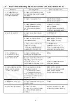
Troubleshooting Guide
Symptom
Checking Items
Repair Items
Remarks
FL display blinking with
abnormal segment when
power ON the set or "F61"
Check the soldering of the SMPS
P. C.B.
x
Is there any solder crack at area
(Q5860,Q5861, Q5862,TH5860)
x
Check all the supply line 30V
x
Is there any solderability at area
of feedback circuit
x
Check feedback circuit (IC5801,
Q5802, D5806, PC5720, D5725)
Tou ch-up the solder crack area/
Change the defective parts.
x
Q5860,Q5861,Q5862,TH5860
(Tem perature Detect)
x
QR5801 & QR5802 ( 30V
Detect)
x
Tou ch-up
the
necessary
areas
x
IC5801,
D5806,
Q5802,
PC5720, D5725
SMPS
P. C.B.
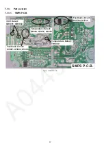
Refer to
Figure 2
First Power ON Display
immediate show "F61".
Check Speaker output by using
multi-meter,
x
If there is a DC Voltage around
30V
x
Check Output IC (Pin 10 &
14) which have DC Voltage at
Speaker output short to
Vdd/Vss
x
If shorted that means D-Amp
damage already.
Change the defective parts.
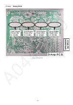
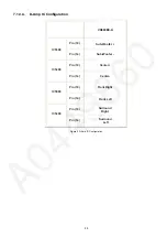
D-AMP IC:
IC5000/IC5200/IC5300/IC5400
P/N = C1BA00000492
For Configuration
Refer to Figure 5
D-AMP
P. C.B.
Refer to
Figure 3
Power ON for a while then
only trigger "F61".
(Symptom always happen)
Check the fan connection &
feedback loop:
x
If the fan not proper connected,
"F61" will trigger when the
volume increase.
x
If the fan is not working, check
for fan circuit.
Check the soldering of the SMPS
P. C.B.
x
Is there any solder crack at area
(Q5860,Q5861, Q5862,TH5860)
x
C
x
+18V at ZJ2701 (Pin 8 & 9)
heck all the supply line
30V
Re-connect the Fan to CN2810
Fan
Q2948 & Q2949
circuit: Q2942, Q2943,
Touch-up the solder crack area/
Change the defective parts.
x
Q5860,Q5861,Q5862,TH5860
(Tem perature Detect)
x
QR5801 & QR5802 ( 30V
Detect)
Feedback Circuit: IC5801, Q5802
PC5720, D5725, D5806
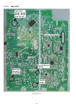
Main
P. C.B.
D-Amp
P. C.B.
Refer to
Figure 4
Refer to
Figure 3
Power ON for a while and
then trigger "F76"
Check all supply voltages as
follows:
Step 1: Check for supply voltages
from SMPS P. C.B to Main
P. C.B at pin 2,5,8,9 of CN5802.
If there are supply voltages,
proceed to Step 2.
If no voltages detected, check wire
connection and circuitry connection
from SMPS P. C.B.
Step 2: Check if there is supply
voltages for Vp, FL1 & FL2
CN2807
x
If there is supply voltages of
+2.7V at CN2801, Pin 19 & 17
+5V at CN2801, Pin 26
x
If t
+5V at CN2807, Pin 5
here is supply voltages of
9V at CN6001
Check and change the possible
defective parts.
x
FP2901 (Fuse Protector),
T2900, D2901
x
IC4000 (Switching Regulator IC)
& related regulator circuit
components
Refer to
Figure 4
Main
P. C.B.
Summary of Contents for SA-VK880EE-K
Page 14: ...14 5 Location of Controls and Components 5 1 Main Unit Key Button Operation ...
Page 15: ...15 5 2 Remote Control Key Button Operation ...
Page 16: ...16 5 3 Disc Information 5 3 1 Disc Playability Media ...
Page 38: ...38 6 5 6 Deck Mechanism Error Code Table ...
Page 49: ...49 ...
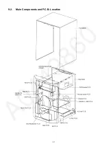
Page 51: ...51 9 2 Main Components and P C B Location ...
Page 120: ...120 ...
Page 122: ...122 ...
Page 148: ...148 ...
Page 172: ...172 MMH0907 ...

