background image

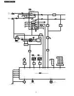
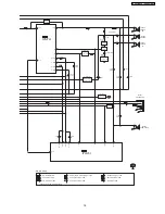
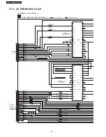
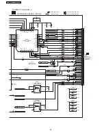
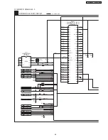
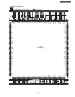
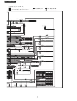
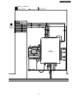
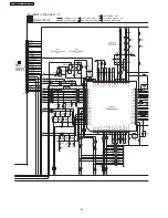
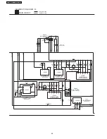
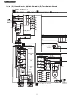
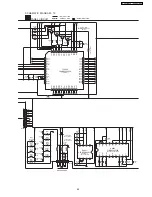
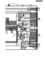
SCHEMATIC DIAGRAM - 8

DVD MODULE (DV2) CIRCUIT

: +B SIGNAL LINE

: CD-DA SIGNAL LINE

: DVD AUDIO SIGNAL LINE

: DVD VIDEO SIGNAL LINE

D+3.3V

I/O

D+1.2V

I/O

AUDIODIGITAL

I/O

ADOUT0

I/O

ADOUT1

I/O

ADOUT2

I/O

DMIXOUT

I/O

C

I/O

Y

I/O

CR/PR/R

I/O

CB/PB/B

I/O

Y/PY/G

I/O

SRCK

I/O

LRCK

I/O

ADAC-CLK

I/O

FODRV

I/O

TRDRV

I/O

AD0

I/O

VIN1

I/O

VIN2

I/O

VIN3

I/O

VIN4

I/O

VIN5

I/O

VIN6

I/O

VIN7

I/O

VIN8

I/O

VHALF

I/O

VREFH

I/O

LPC02

I/O

LPC2

I/O

LPC01

I/O

LPC1

I/O

RFINP

I/O

RFINN

I/O

KMODE

CP8034

RA8032

(4.7K x 2)

RA8031

(4.7K x 2)

L8302

J0JCC0000079

L8301

G1C100KA0055

C8302

6.3V33

C8301

6.3V220

K8325

ERJ2GE0R00V

R8325

160

R8326

0 (GCP)

10 (GCS)

K8321

ERJ2GE0R00V

R8321

160

R8322

10

K8341

ERJ2GE0R00V

R8341

82

K8335

ERJ2GE0R00V

K8331

ERJ2GE0R00V

R8335

82

R8331

160

R8332

10

CP8204

CP8203

TP8201

CP8202
CP8201

C8218

1

C8217

1

VIN1
VIN2
VIN3
VIN4
VIN5
VIN6
VIN7
VIN8
VHALF

VREFH
LPC02
LPC2
LPC01
LPC1
RFINP
RFINN

VIN1
VIN2
VIN3
VIN4
VIN5
VIN6
VIN7
VIN8
VIN5
VIN6

FDT8

C8228

1

C8201

6.3V100

C8202

100P

C8206

6.3V1

L8201

G1C100K00020

L8202

J0JCC0000079

R8232

10K

CP8231

CP8233

CP8234

CP8236

CP8235

C8233

4700P

C8237

1000P

C8238

820P

C8236

1000P

C8235

1000P

R8233

15K

R8236

8.2K

R8235

8.2K

C8232    0.1

C8234    0.1

C8303    0.1

C8312

6.3V1

C8304    6.3V1

C8311    0.1

R8311        2.4K

R8312        1K

R8313        24K R8314        0

LB8401

ERJ3GEYJ151V

C8400

15P

R8621

1M

R8622        470

C8622    5P

C8621    39P

X8621

H0J270500064

C8014

0.1

R8401

47K

RA8401

(100 x 2)

RA8402

(100 x 2)

R8402       100

R8403       100

R8404       100

R8041

33

C8016        6.3V1

C8015        6.3V1

C8017

0.1

CP8040

C8002

330P

C8001

100P

LB8002

J0JHC0000045

LB8001

J0JHC0000045

CP8041

CP8043

CP8044

CP8045

CP8046

CP8047

R8315        6.8

C8208    0.1

C8307    0.1

88

SA-VK91DGCS / SA-VK91DGCP

Summary of Contents for SA-VK91DGCS

Page 1: ...Ltd RCB Registration Number 197701580H All rights reserved Unauthorized copying and distribution is a violation of law SA VK91DGCS SA VK91DGCP Colour S Silver Type Audio performance Amplifier Input sensitivity Input impedance Aux 250 mV 20 kΩ Phone jack Terminal Stereo 3 5 mm jack Mic jack Sensitivity 0 7 mV 600 Ω Terminal Mono 6 3 mm jack 2 system n CASSETTE DECK SECTION Type Auto Reverse Track s...

Page 2: ...Safety Precautions 4 4 1 General Guidelines 4 PB output level 0 7 Vp p 75 Ω PR output level 0 7 Vp p 75 Ω Terminal Pin jack Y green PB blue PR red 1 system n GENERAL Power supply AC 110V 127V 220 230V 240V 50 60Hz Power consumption 313 W Power consumption in standby mode 1 W Dimensions WxHxD 250 x 330 x 372 mm Mass 9 6 kg Operating temperature range 5 C to 35 C Operating humidity range 5 to 90 RH ...

Page 3: ...rocedure for removing CD loading mechanism 41 17 9 CR16 mechanism disassembly procedure 41 17 10 CR16 MECHANISM ASSEMBLY PROCEDURE 47 17 11 Disassembly for Traverse Unit 58 17 12 Disassembly of Deck Mechanism Unit 60 17 13 Replacement for the cassette lid ass 馳 64 17 14 Counter measure for tape trouble 65 18 Service Position 66 18 1 Checking Procedure 66 18 2 Checking the Main P C B Speaker P C B ...

Page 4: ...damage if for example the positive and negative speaker connection wires are shorted or if speaker systems with an impedance less than the indicated rated impedance of the amplifier are used If this occurs follow the procedure outlines below 1 Turn off the power 2 Determine the cause of the problem and correct it 3 Turn on the power once again after one minute Note When the protection circuitry fu...

Page 5: ... component or semiconductor equiped assembly drain off any ESD on your body by touching a known earth ground Alternatively obtain and wear a commercially available discharging ESD wrist strap which should be removed for potential shock reasons prior to applying power to the unit under test 2 After removing an electrical assembly equiped with ES devices place the assembly on a conductive surface su...

Page 6: ...lting point is 50 70 F 30 40 C higher Please use a high temperature soldering iron In case of soldering iron with temperature control please set it to 700 20 F 370 10 C Pb free solder will tend to splash when heated too high about 1100 F 600 C When soldering or unsoldering please completely remove all of the solder on the pins or solder area and be sure to heat the soldering points with the Pb fre...

Page 7: ... an anti static flexible cable After replacing and connecting to the flexible board cut the anti static flexible cable Refer to Fig 7 1 Fig 7 1 7 2 Replacing Precautions for Optical Pickup Unit DVD CD Optical Pickup The optical pickup by which part supply was carried out attaches the short clip to the flexible board for laser diode electrostatic discharge damage prevention Please remove the short ...

Page 8: ...1 Do not disassemble the optical pick up unit since radiation from exposed laser diode is dangerous 2 Do not adjust the variable resistor on the pick up unit It was already adjusted 3 Do not look at the focus lens using optical instruments 4 Recommend not to look at pick up lens for a long time CAUTION THIS PRODUCT UTILIZES A LASER USE OF CONTROLS OR ADJUSTMENTS OR PERFORMANCE OF PROCEDURES OTHER ...

Page 9: ...9 Accessories Remote control AC power supply cord FM indoor antenna AM indoor antenna Video cable AC Plug Adaptor For GCP only 9 SA VK91DGCS SA VK91DGCP ...

Page 10: ...10 Operation Procedures 10 SA VK91DGCS SA VK91DGCP ...

Page 11: ...11 SA VK91DGCS SA VK91DGCP ...

Page 12: ...11 Disc information 12 SA VK91DGCS SA VK91DGCP ...

Page 13: ...13 SA VK91DGCS SA VK91DGCP ...

Page 14: ...r products like DVD players Therefore we used to have problems such as follow There was no common play list or attached information on contents which is called metadata The data compression method differed according to the equipment As the number of CD ROMs recorded increased retrieved the contents became more difficult Because display and operation methods were different depending on the equipmen...

Page 15: ...of the HighMAT standard 1 Recording medium CD R CD RW Supports ISO 9660 Level Expanded Joliet For multiple session 2 Support data format Level 1 player WMA MP3 MPEG 1 Audio Layer 3 Level 2 player WMA MP3 MPEG 1 Audio Layer 3 JPEG Level 3 player WMA MP3 MPEG 1 Audio Layer 3 JPEG WMV MPEG4 optional 3 Limitation of data format 15 SA VK91DGCS SA VK91DGCP ...

Page 16: ...on files Maximum 200 Total number of directories Maximum 400 Length of a file name Maximum 108 characters Unicode Total number of play lists Maximum 200 Number of contents in the playlist Maximum 900 5 Composition of HighMAT disc Menu Classified for the navigation of the HighMAT digital contents When menu selected its submenu or the play list will be displayed Play list A list in which one or more...

Page 17: ...13 Procedure for repairing the set 17 SA VK91DGCS SA VK91DGCP ...

Page 18: ... unit Voltage selector is faulty AC inlet JK500 is faulty AC Line filter L500 is faulty Power On switch broken Replace of fuse if found faulty Replace of voltage selector if found faulty Replace of AC Inlet if found faulty or damaged Replace AC Line filter is found faulty or damaged Replace Power On button switch if necessary If conditions as mentioned above is in good condition Check for wire con...

Page 19: ...em Check pin 2 8 9 10 11 for voltages Replace IC5802 if found faulty 2 No output SL SR C signal Check for input signal before troubleshooting for IC5801 IC5801 problem Check pin 1 2 5 for output signal Replace IC5801 if found faulty 13 1 2 Troubleshooting Guide Part 2 Checking Points Possible Faults Possible Reasons Countermeasure Deck Circuit 1 No PLAYBACK PB Rec signal IC1001 problem Check pin 2...

Page 20: ...minal for color difference signal 32 COUT Signal Output Terminal for chroma signal 29 30 MIXOUT1 MIXOUT2 Signal Ouptut Terminal for Y C Mix Signal 24 25 YOUT1 YOUT2 Signal Output Terminal for luminance signal interlaced type 3 12 14 CIN CBIN CRIN Input signal terminal for chroma signal and color difference 5 8 YIN PYIN Input signal terminal for luminance signal 20 SA VK91DGCS SA VK91DGCP ...

Page 21: ...ction damage Confirmation 1 Remove cover of mechanism block so that you will see the lens of optical pickup Confirm emission of laser at the moment when power switch is turned on If there is no laser emission laser diode is faulty Confirmation 2 21 SA VK91DGCS SA VK91DGCP ...

Page 22: ...1 Confirmation of jitter value with test disc Refer below for how to check jitter 2 Lens cleaning 3 Reconfirm jitter value 4 Perform tile adjustment Refer to tilt adjustment 5 Reconfirm jitter value To confirm jitter value while pressing STOP on main unit and 5 on remote controller Unit display jitter value on FL Confirmation 2 If servo is very unstable due to optical error and you cannot confirm ...

Page 23: ...in order to perform self diagnosis and tilt adjustment effectively Especially when NO DISC is displayed be sure to apply the self diagnosis function before replacing with an optical pickup Replacement of optical pickup generally requires when the present value of laser drive exceeds 45 DVD or 45 CD Note Start diagnosis within three minutes after turning on the power as diagnosis fails when the uni...

Page 24: ...the button on the remote controller unit T1_0000_0000 Resetting spindle motor usage time While the spindle motor usage time is displayed press the button on the player and the button on the remote controller unit T2_0000 14 2 1 Cautions to be taken during replacement of optical pickup Optical pickup could be damaged due to the static electricity discharged from human body Wear proper protection ge...

Page 25: ...er 2 Select DVD CD function With no DVD CD inserted in the player press and hold down the button for at least two seconds and press the 0 button on the remote control for at least two seconds in order to display DVD_F_ _ _ 3 Press the button If a memorized error is detected the result of self diagnosis is displayed Ex T H15 If several errors are detected press the button to display each 15 2 2 Re ...

Page 26: ...0 A message is sent during AV task transmission During transmission of a message to AV task F891 Unable to transmit a message to AV task When transmission of a message to AV task starts F893 DVD Module problem Check for firmware version F894 EEPROM failure F895 Firmware compatibility problem Check for firm version for Main DVD Module P C B F897 Initialization is not done properly Follow proper ste...

Page 27: ...D current electricity value 3 CD current electricity value Values are shown in the decimal digit The above example indicates that the current electricity initialization value is 13mA at DVD laser and 32mA at CD laser when laser is turned on Automatically exits the mode after five seconds Measurement of DVD laser current electricity While the player is stopped and no disc is inserted press and hold...

Page 28: ...controller unit Firmware version display rrr 1 _xx 2 y 3 zzz 4 1 Panel computer release number 2 System computer generation 3 System computer model type 4 System computer release number Automatically exits the mode after five seconds Region and firmware display While the player is stopped and no disc is inserted press and hold down the button on the player and the number button 8 on the remote con...

Page 29: ...disabled OPEN CLOSE Operation Lock Function 1 With the SELECTOR on DVD CD and POWER ON hold down the CD PLAY KEY on the main unit and then press the POWER KEY on the remote control for 3 seconds to enter Lock mode B _ _ _ LOCKED_ will be displayed for 3 seconds and the current disc will begin playing 2 Lock mode B primarily controls the selector and disc operations and disenables for the following...

Page 30: ...cedures automatically start when the recovery disc is replayed General CD R disc allows version upgrade process and recovery process making version upgrade through disc simple Recovery process Optimization process of player after replacement of FLASH ROM EEPROM or module circuit board Version upgrade process Renewal of firmware for improvement of operational range and performance 16 3 1 Self Diagn...

Page 31: ...ntroller unit To reset the usage time while the usage time is displayed Laser usage time press both the button on the player and the button on the remote controller unit Spindle motor usage time press both the button on the player and the button on the remote controller unit 2 Purpose of Use To obtain reference data of laser and spindle motor systems during failure diagnosis To check faulty parts ...

Page 32: ...isassembly flow chart The following chart is the procedure for disassembling the casing and inside parts for internal inspection when carrying out the servicing To assemble the unit reverse the steps shown in the chart as below 32 SA VK91DGCS SA VK91DGCP ...

Page 33: ... changer unit Follow the Step 1 Step 2 of Item 17 2 Step 1 Detach FFC Boards CN2811 CN2815 Step 2 Remove 1 screw at rear cabinet as show below Step 3 Lift the DVD changer unit upwards Step 4 Release the claws on both ends and remove the DVD changer unit Step 5 Remove 2 screws Step 6 Remove the mechanism unit cover Step 7 Lay the unit 17 2 Disassembly of Top Cabinet 33 SA VK91DGCS SA VK91DGCP ...

Page 34: ...it as shown below Step 3 Remove 2 screws at the bottom chassis Step 4 Release the 2 claws and then draw the front panel ass y forward Disassembly of Panel P C B Mic P C B Step 5 Remove 7 screws Step 6 Detach FFC board CP6803 CP6800 Step 7 Release 3 catches 17 4 Disassembly for Panel P C B MIC P C B Tact Switch P C B 34 SA VK91DGCS SA VK91DGCP ...

Page 35: ...s draw the rear panel to remove it Step 11 Disconnect connector W601B Step 12 Remove 5 screws Step 13 Draw Tact Switch P C B forward 17 4 1 Disassembly of Lid Follow the Step 1 Step 2 of Item 17 2 Follow the Step 1 Step 4 of Item 17 3 Follow the Step 1 Step 4 of Item 17 4 Step 1 Remove 2 screws Step 2 Lift the spring sideward Step 3 Remove Lid Note Do not misplace the spring 17 5 Disassembly of Ma...

Page 36: ...he Step 1 Step 3 of Item 17 5 Step 1 Remove the 2 screws Step 2 Detach cables CN5802 CN5803 Step 3 Remove the 2 screws 17 5 2 Disassembly of Speaker P C B Follow the Step 1 Step 2 of Item 17 2 Follow the Step 1 Step 4 of Item 17 3 Follow the Step 1 Step 4 of Item 17 4 Follow the Step 1 Step 3 of Item 17 5 Step 1 Detach cable CN953 CN950 CN951 Step 2 Detach cable CN5807 CN5810 Step 3 Lift up Speake...

Page 37: ...egulator Step 3 Break the joint with a metal cutter as shown below Step 4 Unsolder the terminals of Power Amp IC replace the component Step 5 Fix back the bottom chasis with a screw as shown NOTE Insulate Power P C B with insulation material to avoid short circuit 17 5 4 Disassembly of Transformer P C B Voltage Selector P C B Follow the Step 1 Step 2 of Item 17 2 Follow the Step 1 Step 4 of Item 1...

Page 38: ...roove opens Step 1 Pull out FFC Step 2 Disconnect connector CN950 CN951 Step 2 Remove DVD traverse deck by rotating to the arrow direction 17 6 Replacement for traverse deck 17 7 Replacement for optical pickup unit DVD mechanism Follow the Step 1 Step 2 of Item 17 2 Follow the Step 1 Step 7 of Item 17 3 Follow the Step 1 Step 2 of Item 17 6 38 SA VK91DGCS SA VK91DGCP ...

Page 39: ...not to lose them Step 6 Remove the dvd module board and turn it over Step 7 Pull FFC out from the connector Note Insert a short pin into FFC of the optical pickup See Notice on handling of the optical pickup Step 8 Rotate the traverse deck B to the arrow direction and shift the optical pickup to the furthest backward Step 9 Remove 1 screw 39 SA VK91DGCS SA VK91DGCP ...

Page 40: ...emove the catch of the drive rack and take out the drive rack Step 11 Place the convex part of an optical pickup to the concave part of a traverse base then take out the optical pickup 40 SA VK91DGCS SA VK91DGCP ...

Page 41: ...of gear for servicing perform the procedures as follows In case of re servicing the same set the gear for servicing may be took off because it had been used So the gear for servicing must be stored 1 Remove the gear attached to top cover of CD loading mechanism 2 Insert the hexagonal wrench 2 5mm into the gear 3 Disassemble the body and take out CD loading mechanism 4 Perform disassembly according...

Page 42: ...42 SA VK91DGCS SA VK91DGCP ...

Page 43: ...17 9 3 Replacement for the traverse deck Follow the Step 1 Step 10 of item 17 9 2 43 SA VK91DGCS SA VK91DGCP ...

Page 44: ...17 9 4 Disassembly for CD loading unit Follow the Step 1 Step 10 of item 17 9 2 Follow the Step 1 Step 3 of item 17 9 3 44 SA VK91DGCS SA VK91DGCP ...

Page 45: ...45 SA VK91DGCS SA VK91DGCP ...

Page 46: ...46 SA VK91DGCS SA VK91DGCP ...

Page 47: ...nd or oil must be applied when some specific parts are changed 1 Floil grease VFK1298 The floil grease must be applied to tray tray L and tray R 2 Hanarl oil VFK1700 The hanarl oil must be applied to any parts with grease other than the said parts 47 SA VK91DGCS SA VK91DGCP ...

Page 48: ...48 SA VK91DGCS SA VK91DGCP ...

Page 49: ...49 SA VK91DGCS SA VK91DGCP ...

Page 50: ...50 SA VK91DGCS SA VK91DGCP ...

Page 51: ...51 SA VK91DGCS SA VK91DGCP ...

Page 52: ...52 SA VK91DGCS SA VK91DGCP ...

Page 53: ...53 SA VK91DGCS SA VK91DGCP ...

Page 54: ...54 SA VK91DGCS SA VK91DGCP ...

Page 55: ...55 SA VK91DGCS SA VK91DGCP ...

Page 56: ...56 SA VK91DGCS SA VK91DGCP ...

Page 57: ...57 SA VK91DGCS SA VK91DGCP ...

Page 58: ... Follow the Step 1 Step 10 of item 17 9 Follow the Step 1 Step 3 of item 17 10 17 11 Disassembly for Traverse Unit 58 SA VK91DGCS SA VK91DGCP ...

Page 59: ...59 SA VK91DGCS SA VK91DGCP ...

Page 60: ...p 2 Remove 2 screws Step 3 Remove the 2 claws and then draw the front panel ass y Step 4 Detach FFC Board CN2811 CN2815 Step 5 Detach flat cable wire CN5806 Step 6 Push the lever upward and then open the cassette lid ass y For DECK1 and DECK2 Step 7 Remove the 5 screw 17 12 Disassembly of Deck Mechanism Unit 60 SA VK91DGCS SA VK91DGCP ...

Page 61: ... one of DECK 2 perform the same procedures Step 1 Release the 2 claws and then remove the head connector Step 2 Remove 6 screws Step 3 Remove the sub chassis Disassembly of pinch roller ass y head block Step 12 Release the 2 claws and then remove the pinch roller R F Step 13 Release ther 2 claws and then remove the head connector Step 14 Remove 2 screws 17 12 1 Replacement for the CD motor ass y c...

Page 62: ...the flywheel R Step 6 Release the claw of tape side and then remove the winding lever and spring Step 7 Remove the flywheel F Installation of the belt Step 1 The boss and marking should be positioned horizontally 62 SA VK91DGCS SA VK91DGCP ...

Page 63: ...5 Install the winding lever and spring while pressing the winding arm in the direction of arrow Step 6 Install the flywheel R Step 7 Put the capstan belt A temporarily as shown below Step 8 Put the capstan belt B on the motor ass y pulley Step 9 Install the sub chassis to the mechanism and then tighten screws 63 SA VK91DGCS SA VK91DGCP ...

Page 64: ...17 13 Replacement for the cassette lid ass y Follow the Step 1 Step 2 of Item 17 2 Step 1 Force the lever upward open the cassette lid ass y For DECK1 and DECK2 Step 2 Lift up the cassette lid ass y in the direction of arrow For DECK1 and DECK2 Step 3 Remove the cassette lid ass y For DECK1 and DECK2 64 SA VK91DGCS SA VK91DGCP ...

Page 65: ... cannot be removed from the deck since the tape is caught by the capstan or pinch roller during playback or recording rotate the flywheel F in the direction of the arrow to remove the tape Step 2 Force the lever upward and open the cassette lid ass y Take the cassette tape off 65 SA VK91DGCS SA VK91DGCP ...

Page 66: ...ction 17 18 2 Checking the Main P C B Speaker P C B Power P C B Sub Power P C B Transformer P C B Voltage Selector P C B and AC Inlet P C B 1 Remove Top Cabinet and Rear Panel 2 Remove DVD Mechanism Unit 3 Connect FFC board CN2810 CN2813 from DVD Mechanism Unit 66 SA VK91DGCS SA VK91DGCP ...

Page 67: ...hanism Unit 3 Remove volume knob at front panel 4 Remove Panel P C B Mic P C B Tact Switch P C B 5 Remove Deck Mechanism P C B 6 Use the extension cable REEX0310 10 Pins to reconnect CP6800 Panel P C B and CN971 Deck Mechanism P C B Service Tools Extension FFC Panel P C B Deck Mechanism P C B REEX0310 10 Pins 67 SA VK91DGCS SA VK91DGCP ...

Page 68: ... 1 Playback the azimuth adjustment portion 8 kHz 20dB of the test tape QZZCFM in the forward play mode Vary the azimuth adjustment screw until the output of the R CH PB OUT R are maximized 2 Perform the same adjustment in the reverse play mode 3 After the adjustment apply screwlock to the azimuth adjusting screw 19 1 2 Tape Speed Adjustment Deck 1 2 1 Set the tape edit button to NORMAL position 2 ...

Page 69: ...rom AM SG 4 Adjust Z102 so that the output frequency is maximized in Fig 6 Fig 5 Fig 6 19 2 2 AM RF Adjustment 1 Connect the instrument as shown in Fig 7 2 Set the unit to AM mode 3 Set AM SG to 520kHz 4 Receive 520kHz in the unit 5 Adjust Z101 OSC so that the EVM AC is maximized 6 Set AM SG to 600Hz 7 Receive 600Hz in the unit 8 Adjust Z101 ANT so that the EVM SG is maximized 9 Set AM SG to 520kH...

Page 70: ...19 3 1 Cassette Deck Section 19 3 2 Adjustment Point 19 3 Alignment Points 70 SA VK91DGCS SA VK91DGCP ...

Page 71: ... 13 15 17 18 252 254 256 217 220 221 223 224 226 228 230 233 237 238 249 251 MDQ0 MDQ15 MA0 MA11 DQM0 DQM1 BA0 BA1 NWE NCAS NRAS NCSM MCK MDQ0 MDQ15 MA0 MA11 LDQM UDQM BA0 BA1 NWE NCAS NRAS NCSM CLK ACT T ACT T ACT F ACT F A3 A2 A1 H1 H1 H2 H2 H3 H3 H VO3 VO3 VO2 VO2 VO1 VO1 FG MUTE3 DRV1 DRV6 DRV8 DRV0 DAC1 PWM0 VHALF AD1 AD2 VCOF AD4 COIL_W COIL_V COIL_U HU HU HV HV HW HW H SW FEED FEED 15 1 24 ...

Page 72: ...8 13 12 11 10 7 6 LD T2 T1 MON F2 F1 RFN RFP T4 T3 GAIN H L 11 4 8 6 10 2 LD F1 F E F2 MON LPC01 DRV3 AD0 VIN2 VIN1 LPC1 VIN8 VIN7 RFINN RFINP VIN4 VIN3 DRV7 LPC02 VIN5 VIN9 VIN10 VIN6 LPC2 82 14 Q8562 SWITCH Q8551 SWITCH Q8552 QR8571 SWITCH SUPPLY CONTROL 143 SWITCH IC8611 C3EBGZ000001 59 60 6 5 SCL SDA P9 P8 EEPROM IC NOT SUPPLIED IC8001 MN2DS0003APH DV2 1 LSI 72 SA VK91DGCS SA VK91DGCP ...

Page 73: ...151 152 156 158 48 ZFLGA DATA4 ZFLAG 31 171 ADOUT3 55P13 QR8420 AUDIO MUTING SWITCH IC8451 C0FBBK000036 A D CONVERTER IC8001 MN2DS0003APH DV2 1 LSI Q8560 SWITCH Q8550 SWITCH B CMD P1 70 C OUT 32 CR OUT 17 CB OUT 19 Y OUT1 25 PY OUT1 22 MIX OUT1 30 JK2802 VIDEO G C Y JK2801 S VIDEO 5 Y IN 3 C IN 14 CR IN 12 CB IN 8 PY IN 2 VMUTE1 MIX OUT2 29 PY OUT2 21 Y PB PR Y OUT2 24 VMUTE WIDE Q2810 INVERTER SW...

Page 74: ...E S952 HALF DECK1 89 INTERFACE Z971 S975 RECINH_F S972 HALF S971 MODE S974 RECINH_R DECK2 90 C2CBJG000460 MICROPROCESSOR IC6800 Q6835 SWITCH DMT 51 Q2806 SWITCH 44 DVD_MUTE ZFLAG VOLUME JOG VR6800 75 VOL_B 76 VOL_A Z6800 REMOTE SENSOR 18 RMT WIDE 47 WIDE_I VMUTE 73 VMUTE Q6812 Q6811 SWITCH IC971 CNB13030R2AU PHOTO INTERRUPTOR PHOTO_2 32 PHOTO_1 31 Q6810 Q6816 SWITCH IC951 CNB13030R2AU PHOTO INTERR...

Page 75: ..._SB 7 8 EXIN1 2 72 73 IN_C 6 FOUT1 28 OUTFL R 39 36 FIN4 3 40 37 OUTLS R 25 23 49 ASP_CK 48 ASP_DA CTR INCA 77 SUBW INSUBA 80 INC1 2 65 66 30 TU_SDA 27 TU_SD 28 TU_ST DO 29 TU_SCL TO TUNER PAD ASP_CLK 46 ASP_DA 45 LOUT LOUT1 2 59 60 Q2815 60 SUB_MUTE Q2825 59 MUTE_SR Q2818 Q2816 MUTING SWITCH MUTING SWITCH MUTING SWITCH MUTING SWITCH FR_L R FOUT4 3 41 38 2 6 1 7 SURRL R IC2811 C0AABB000117 HP AMP ...

Page 76: ...000292 ANALOG SWITCH 13 14 12 1 3 15 4 2 5 D6808 D6811 B Q6821 Q6824 SWITCH 24 25 84 85 LED1 4 9 10 11 77 PARTY 34 77 64 63 IC2813 C1BB00000801 KARAOKE IC 33 32 52 KAT_LAT 54 KAT_CLK 53 KAT_DAT 75 74 LOUT D951 PL971 D971 PL970 Q6814 SWITCH 80 PLUNGER2 PLUNGER SWITCH Q6834 Q6813 SWITCH 50 PLUNGER1 PLUNGER SWITCH Q6833 Q2840 SWITCH 63 SURR_C Q2839 SWITCH XCOUT 11 XCIN 10 X6801 6 MBP1 7 MBP2 Q6001 Q6...

Page 77: ...7 SDATA 45 FL_DA 8 CS 43 FL_CS 6 RESET 42 FL_RST 5 FL DISPLAY IC6803 C0HBB0000039 OUT2 2 OUT1 4 RM11 UP DOWN MOTOR 9 R_IN 7 F_IN 26 UP DOWN F 20 UP DOWN R IC11 C0GAG0000007 UP DOWN MOTOR DRIVER M OUT2 2 OUT1 4 9 R_IN 7 F_IN 3 OP CL_FWD 2 OP CL_REV RM21 LOADING MOTOR IC21 C0GAG0000007 LOADING MOTOR DRIVER M DVD_PCNT 68 B Q6820 PCONT SWITCH L2805 L2802 2 5 4 2 5 4 1 1 B IC2801 IC2806 C0CBADG00005 5V...

Page 78: ...UT 8 C OUT 5 FILTER 22 LR IN 23 C OUT FILTER SOL R 1 2 FILTER 26 25 SIL R SURRL R CENTER SUBWOOFER JK5802 SURR L R LCH B Q6803 Q6804 PCONT SWITCH Q5803 MUTING SWITCH MUTE_H 56 MUTE_H D5846 D5847 D5844 FP5801 D5836 D5839 B JK500 AC INLET T502 Z501 F1 L500 SUB TRANSFORMER F3 F4 D5831 D5832 D5812 Vin1 12 Vin1 6 MAIN TRANSFORMER TO FL DISPLAY Q5816 REGULATOR FP5802 Q5815 REGULATOR B Q5817 T501 REGULAT...

Page 79: ... 14 VCC LOW 5 Di SENS 13 VCC LOW 4 D5805 D5806 D5850 D5851 D5849 D5848 FILTER SIGNAL LINES Indicates the Pin No of Right Channel MAIN SIGNAL LINE FM AM SIGNAL LINE NOTE Signal Lines are applicable to the Left Channel only AUX SIGNAL LINE CD DA AUDIO VIDEO SIGNAL LINE DVD AUDIO SIGNAL LINE DVD VIDEO SIGNAL LINE RECORD SIGNAL LINE PLAYBACK SIGNAL LINE MIC SIGNAL LINE 7 AC IN IC5805 RSN312H24 P POWER...

Page 80: ...tch VR6800 VR Volume Jog VR6801 VR Mic The voltage value and waveforms are the reference voltage of this unit measured by DC electronic voltmeter high impedance and oscilloscope on the basis of chassis Accordingly there may arise some error in voltage values and waveforms depending upon the internal impedance of the tester or the measuring unit CD FM Importance safety notice Components identified ...

Page 81: ... 0 22 L3 J0JBC0000105 T F F T HFM TA TB TD TC FE2 FE1 GND IM RF VREF2 RF PIN DVD LD CD LD GND LD DVD GND OEIC VREF1 VCC SUB2 SUB1 PIN CD SW GND IM GND VCC GND GND OUT GND GND TB TA TC TD FE1 FE2 IM RF GND VREF VCC SUB2 SUB1 SW LD CD LD DVD LDGND SCHEMATIC DIAGRAM 1 OPTICAL PICKUP UNIT CIRCUIT B SIGNAL LINE CD DA SIGNAL LINE 2 4 6 5 3 1 15 14 13 12 11 10 2 4 6 8 9 7 5 3 1 17 18 16 16 17 18 19 20 21...

Page 82: ...CH3 4 MUTE4 GND CH3 4 VO3 VO3 VO4 VO4 BIAS1 VIN1 VIN2 OPIN OPIN OPOUT GND PRE FIN VCC CH1 2 MUTE12 GND CH1 2 VO2 VO2 VO1 VO1 TRV INNER SW DV2 TRDRV DV2 FODRV DV2 MUTE12 DV2 CP8252 CP8251 TO SPINDLE PCB LB8271 ERJ3GEY0R00V LB8272 ERJ3GEY0R00V LB8273 ERJ3GEY0R00V R8281 100 R8282 100 C8284 0 01 C8285 0 01 C8286 0 01 C8287 0 1 LB8512 ERJ3GEY0R00V LB8513 ERJ3GEY0R00V LB8511 ERJ3GEY0R00V LB8514 ERJ3GEY0...

Page 83: ... C8501 10 C8505 220P RA8501 56 x 2 D8571 MA2J72800L C8253 0 1 C8274 0 1 C8273 0 1 C8251 6 3V220 C8272 33P C8271 16V47 R8451 0 C8453 10 C8455 0 1 L8420 G1C220KA0055 TP8111 C8112 1 C8113 470P C8111 0 1 L8550 G1C100KA0055 C8561 0 1 C8551 0 1 C8503 0 1 R8559 15K R8558 47K R8557 51 R8556 56 C8553 6 3V47 R8555 2 2 R8553 1K R8552 330 R8551 0 R8554 22 C8552 16V10 R8567 51 R8568 47K R8566 56 C8563 6 3V47 R...

Page 84: ...D DGND DIN1 DIN2 DIN3 ZFLGA VCC AGND VCC AGND VOUT8 NC AGND VCC AGND VOUT7 NC VCOM VOUT1 VOUT2 ZFLG1 ZFLG2 ZFLG3 ZFLG4 ZFLG5 ZFLG6 NC NC VOUT6 VOUT5 VOUT4 VOUT3 ML MC MDI MDO ZERO8 DATA4 ZERO7 NC VCC AGND VCC AGND VCC GND GND VCC OP_CPU CLK DV2 OP_CPU CMD DV2 OP_CPU STAT DV2 LPCO2 DV2 LPCO1 DV2 Y PY G DV2 CB PB B DV2 CR PR R DV2 Y DV2 C DV2 AMUT DV2 A 5V DV2 D 1 2V DV2 AUDIODIGITAL DV2 D8550 MA2S1...

Page 85: ...ACC RDY XBSY A18 A17 A7 A6 A5 A4 A3 A2 A1 A16 XBYTE VSS DQ15 A 1 DQ7 DQ14 DQ6 DQ13 DQ5 DQ12 DQ4 VDD DQ11 DQ3 DQ10 DQ2 DQ9 DQ1 DQ8 DQ0 XOE VSS XCE A0 FDT15 FDT7 FDT14 FDT6 FDT13 FDT5 FDT12 FDT4 FDT11 FDT3 FDT10 FDT2 FDT9 FDT1 FDT8 FDT0 EXADT15 EXADR16 EXADT14 EXADT13 EXADT12 EXADT11 EXADT10 EXADT9 EXADT8 EXADR19 EXADR20 NEXWE EXADR18 EXADR17 EXADT7 EXADT6 EXADT5 EXADT4 EXADT3 EXADT2 EXADT1 EXADT0 P...

Page 86: ...1 MDQ2 MDQ3 MDQ4 MDQ5 MDQ6 MDQ7 DQM0 NWE NCAS NRAS NCSM BA0 BA1 MA10 MA0 MA1 MA2 MA3 C8051 6 3V1 C8052 0 1 C8053 220P C8054 6 3V1 C8055 6 3V1 C8056 0 1 C8057 2200P C8011 6 3V1 C8010 0 1 C8008 0 1 C8007 0 1 C8005 0 1 C8009 0 1 C8006 0 1 C8004 0 1 C8003 2200P RA8011 82 x 4 RA8012 82 x 4 RA8013 82 x 4 C8025 0 1 C8022 0 1 C8023 6 3V1 C8024 2200P C8026 6 3V1 C8027 0 1 C8028 6 3V1 C8013 0 1 C8012 0 1 IC...

Page 87: ... VIN1 VIN2 VIN3 VIN4 RFINP RFINN MUTE12 CP8002 TP8220 TP8219 TP8218 TP8217 TP8216 TP8215 TP8214 TP8213 CP8003 RAM_CD TRV I SW FGENB MUTE3 HFMON M 9 12VCTL DRV1 DRV0 PNRST CP8001 FG YC_H CPU CMD CPU STAT CPU CLK KMODE CLKSEL RGBH MDQ9 MDQ6 MDQ8 MDQ7 DQM1 DQM0 NWE NCAS NRAS NCSM CLK MA9 MA11 MA8 MA10 BA0 BA1 MA7 MA0 MA6 MA1 MA5 MA2 MA4 MA3 FDT0 FDT15 FDT1 FDT14 FDT2 FDT13 FDT3 FDT12 FDT4 FDT11 FDT5 ...

Page 88: ...R8335 82 R8331 160 R8332 10 CP8204 CP8203 TP8201 CP8202 CP8201 C8218 1 C8217 1 VIN1 VIN2 VIN3 VIN4 VIN5 VIN6 VIN7 VIN8 VHALF VREFH LPC02 LPC2 LPC01 LPC1 RFINP RFINN VIN1 VIN2 VIN3 VIN4 VIN5 VIN6 VIN7 VIN8 VIN5 VIN6 FDT8 C8228 1 C8201 6 3V100 C8202 100P C8206 6 3V1 L8201 G1C100K00020 L8202 J0JCC0000079 R8232 10K CP8231 CP8233 CP8234 CP8236 CP8235 C8233 4700P C8237 1000P C8238 820P C8236 1000P C8235...

Page 89: ...K R2238 22K C2223 47P R2237 22K R2634 0 R2633 0 C2227 50V10 R2262 3 3K C2301 6800P R2967 100K R2244 12K C2129 0 15 C2226 0 15 R2241 12K R2143 12K TUNER_GND M 9V TUNER_RCH TUNER_DO ST TUNER_LCH TUNER_SD TUNER_DI TUNER_CLK PORT_SEL TUN_R 9V TU_ST DO TUN_L TU_SD TU_SDA TU_SCL KA_CLK KA_DAT KA_LAT ASP_DA ASP_CK VMUTE MUTE_L MUTE_H HP_MUTE MUTE_C 9V MUTE_SUR SUB BGND MUTE_SUB SPEA VREF LED9V MUTEA 15V ...

Page 90: ...V1 R2315 22K C2313 22P R2314 22K R2313 22K R2322 22K R2325 56K R2323 1 8K C2317 50V3 3 R2321 56K R2320 22K R2636 0 R2312 27K C2311 18P R2142 47K R2242 47K C2246 0 022 C2149 0 022 R2646 0 R2635 0 R2317 47K C2316 0 1 R2165 4 7K R2263 4 7K LINE_LIN LINE_RIN 9V EXT_R PARTY LS_RS EXT_L 9V 9V KA_LOUT 9V KA_ROUT DSP_C SFC 9V IC2818 C0JBAR000292 ANALOG SWITCH IC Z0 Z Z1 Y0 Y1 X0 X1 X Y C C VCC VCC SUR SUR...

Page 91: ...50V2 2 C2901 560P R2991 0 R2978 0 R2979 0 R2980 0 R2981 0 R2982 0 R2843 220 R2983 0 R2984 0 R2985 0 R2986 0 R2987 0 7 5V LOAD_GND CHANGE_SW GND UP DOWN_F UP DOWN_R BOTTOM POSITION 5V OPEN_SW OP CL_FWD OP CL_REV ST_SW PLAY_SW CD8V CHANGE_SW UP DOWN_F UP DOWN_R BOTTOM_SW POSITION VREF OPEN_SW OP CL_FWD OP CL_REV ST_SW PLAY_SW KA_ROUT KA_LOUT KA_RIN KA_LIN MIC 15V KA_DAT KA_CLK KA_LAT CN2810 TO CD LO...

Page 92: ..._LIN LINE_RIN PBL PBR AUX_L AUX_R TUN_L TUN_R MIX_L MIX_R CENTER SUBW FR FL DVD_CLK DVD_CMD DVD_STA SR SL EXT_L EXT_R KA_LIN KA_RIN DSP_C LS_RS LS_RS ASP_CK ASP_DA 9V 9V FR_L FR_R CN2815 IC2815 C1BB00000845 ASP IC Q2839 Q2840 INA1 INA2 INB1 INB2 INC1 INC2 IND1 IND2 INE1 INE2 EXIN1 EXIN2 INFLA INFRA INCA INLSA INRSA INSUBA AOUT1 AOUT2 INFLB INFRB INL_SB INR_SB MAIN CIRCUIT SCHEMATIC DIAGRAM 12 B SI...

Page 93: ...K R2306 1 8K R2404 1 8K R2609 8 2K R2120 1K R2264 2 2K R2301 10K C2113 50V4 7 R2167 2 2K C2115 100P C2116 33P R2122 47K C2215 16V47 R2233 0 R2221 47K C2214 33P C2213 100P R2219 1K C2211 50V4 7 C2872 0 01 R2218 220K R2642 0 R2918 220K R2921 3 3K R2853 3 3K MUTE_SUB MUTE_SUR 9V 9V Q2815 Q2816 Q2825 Q2818 Q2819 IC2811 C0AABB000117 HP AMP IC MAIN CIRCUIT SCHEMATIC DIAGRAM 13 MAIN SIGNAL LINE B SIGNAL ...

Page 94: ...16V47 9V 9V MUTEA MUTE_C HP_MUTE HPR HPL 9V 15V FR_L FR_R AGND DCDET MUTE_H 15V FRL FRR LSURR RSURR CENTER SUBWOOFER DCDET MUTE_H AGND SUB B 9V 9V CD8V SW5V FAN LED9V MOT10V 9V 9V DIGITAL_GND 8V SW5V FAN LED9V MOT10V CN2801 CN2802 TO POWER CIRCUIT CP5801 ON SCHEMATIC DIAGRAM 24 TO POWER CIRCUIT CP5802 ON SCHEMATIC DIAGRAM 24 IC2812 KIA4558FEL DUAL OP AMP IC Q2821 Q2820 B1ABEB000001 MUTING SWITCH Q...

Page 95: ... 0 C2823 10V220 C2824 16V47 C2825 16V47 C2826 0 01 C2827 22P C2828 16V47 C2829 0 01 C2830 16V47 C2831 0 01 R2340 0 R2341 0 DVD_STA DVD_CMD DVD_CLK MGND M 9V MGND M 9V DGND D 1 2V AGND D 1 2V AGND A 5V AGND A 5V DGND D 5V DGND D 5V DGND DGND ZFLAG SUBW ADACGND SR ADACGND SL ADACGND FR ADACGND FL ADACGND MIXR ADAC5V MIXL ADAC5V C YGND Y YGND CR PR R YGND CB PB B YGND CENTER ADACGND PY Y G YGND DVD_S...

Page 96: ...3 D2832 B0ADCJ000020 L2805 G0A101G00022 R2803 1 R2804 1 R2805 1 DVD_PCNT D 1 2V DVD_AC D 5V A 5V DVD_AC 9V 9V MOT10V LED9V SW5V 9V DCDET SUB B MOT10V FAN5V IC2806 IC2801 IC2803 C0DBAZG00033 DC TO DC CONVERTER Q2802 B1ADCF000001 CURRENT LIMITTER IC2802 C0DBAZG00033 DC TO DC CONVERTER IC2807 IC2808 Q2838 B1GBCFJA0015 SWITCH Vin Vout COM 0adj Vsoft Vin Vout COM 0adj Vsoft MAIN CIRCUIT SCHEMATIC DIAGR...

Page 97: ... B0ACCK000005 C2871 16V330 R2913 10K L2820 G0C221KA0007 R2899 4 7K DCDET FAN5V FAN 9V DCDET FAN FAN5V FAN FAN CN2809 CN2806 Q2831 B1ABCF000011 DCDET SWITCH Q2830 Q2829 Q2828 Q2827 Q2826 Q2832 Q2833 Q2837 Q2836 Q2834 Q2835 MAIN CIRCUIT SCHEMATIC DIAGRAM 17 B SIGNAL LINE B SIGNAL LINE D2824 2825 B0ACCK000005 D2819 B0ACCK000005 D2821 B0ACCK000005 D2828 2829 B0ACCK000005 Q2830 B1ADCF000001 FAN MOTOR D...

Page 98: ...6860 4 7K R6861 6 8K R6862 10K C6878 100P C6802 100P R6864 47K R6865 47K C6895 16V10 R6889 18K R6869 3 9K C6888 330P C6887 330P C6886 330P C6885 330P PBL PBR AGND REC_L REC_R 15V REC_01 MOT10V SUB BGND DECK1_H MOT_01 PBL PBR REC_L REC_R 15V REC_01 MOT10V DECK1_H MOT_01 BP SYS6V KEY1 9V MIC PANEL CIRCUIT SCHEMATIC DIAGRAM 18 DGND MICSW MIC_GND DGND MICSW MIC_GND FLD_RST FLD_CS FLD_CK FLD_DA SW5V SW...

Page 99: ...REF E_DA SPE SP_C SP_B SP_A DVREF SPEA DIG03 DIG02 DIG01 DIG00 RESET CS SCK SDATA P1 P0 VCC1 XOUT XIN VSS SEG35 SEG34 SEG33 SEG32 SEG31 SEG30 SEG29 SEG28 SEG27 Vp SEG26 SEG25 SEG24 SEG23 SEG22 SEG21 SEG20 SEG19 SEG18 SEG17 SEG16 SEG15 SEG14 SEG13 SEG12 SEG11 SEG10 SEG9 SEG8 SEG7 SEG6 SEG5 SEG4 SEG3 SEG2 SEG1 SEG0 VCC2 DIG15 DIG14 DIG13 DIG12 DIG11 DIG10 DIG09 DIG08 DIG07 DIG06 DIG05 DIG04 IC6803 C...

Page 100: ...9 0 R6042 4 7K C6014 1000P C6013 56P R6041 4 7K C6015 1000P C6835 39P C6016 56P C6834 39P C6840 15P C6841 15P R6948 680 X6800 X6801 R6951 10M R6952 330 VREF VREF SFC LED3 LED4 DECK1 DECK2 KEY3 KEY2 SPE KEY1 VREF PLAY_SW ST_SW OP CL_REV OP CL_FWD OPEN_SW POSITION DVREF CNVSS RESET SYS6V RMT UP DOWN_R CHANGE_SW DVREF BOTTOM_SW LED1 LED2 UP_DOWN_F TU_SD TU_ST DO TU_SCL TU_SDA DVREF PLUNGER2 PARTY JOG...

Page 101: ...HPL SURR_C TU_SD SFC TU_ST DO TU_SCL PARTY TU_SDA UP DOWN_F DVD_PCNT BOTTOM_SW WIDE_1 CHANGE_SW DC_DET UP DOWN_R DVD_MUTE POSITION DVD_STA OPEN_SW DVD_CMD OP CL_FWD DVD_CLK OP CL_REV DGND ST_SW SW5V PLAY_SW MOT10V PPL2 PPL1 DVREF SUB BGND DECK2 PPHOTO_1 PPHOTO_2 HALF_PB DECK1 DECK2 TU_SCL PARTY TU_SDA UP DOWN_F DVD_PCNT BOTTOM_SW WIDE_1 CHANGE_SW DC_DET UP DOWN_R DVD_MUTE POSITION DVD_STA OPEN_SW ...

Page 102: ...C1004 C1031 10V100 R1016 47 C1027 1000P C1023 1000P C1033 0 018 R1019 3 9K R1022 10K C1035 50V3 3 C1037 50V3 3 C1039 220P C1045 10V22 R1028 8 2K C1041 16V10 C1021 470P C1022 1000P R1010 18K C1042 16V22 R1031 27K R1035 10K R1030 100 C1058 1000P R1090 220 C1046 16V220 R1040 0 C1044 10V33 R1032 10K R1055 2 2K R1098 10K IC1001 AN7348S E1 P B EQ REC AMP ALC TPS AMP C1030 10V100 R1015 47 R1018 3 9K C103...

Page 103: ...K R1060 390 C1055 50V0 1 R1059 10K R1061 0 R1056 220 R1058 2 7K C1053 16V220 PBOUTL PBOUTR AFGND RECINL RECINR B REC_H MO B MO GND DMT DECK1_H BP1 MOTOR Q1014 Q1015 B1ABCF000011 BUFFER AMP Q1012 Q1013 B1ABEB000001 MUTING Q1020 Q1021 B1ABEB000001 MUTING SWITCH Q1016 Q1016 B1GDCFJJ0023 DECK MUTING SWITCH Q1017 B1AARC000002 MOTOR SWITCH Q1017 W1002 R1097 10K C1047 50V1 IC951 CNB13030R2AU PHOTO INTERR...

Page 104: ...R5400 15K R5302 15K TO SPEAKER CIRCUIT CN5809 ON SCHEMATIC DIAGRAM 27 TGND 15V FR_L FR_R AGND AGND LSURR RSURR CENTER S_WOOFER DC_DET MUTE_IN Q5806 Q5805 Q5807 Q5808 Q5809 Q5804 Q5810 Q5811 IC5802 SCHEMATIC DIAGRAM 24 SIL SIR IN_GND C_IN LR_IN VD VD CIN CIN RELAY Di_ SENS Di_ SENS IH_DET DISP_ HMUT COUT COUT GND AC_IN LR_OUT VCC_LOW VCC_LOW C_OUT VCC_Hi VCC_Hi SOR SOL IC5801 RSN309W44B POWER HIC I...

Page 105: ... Q5813 KTC3199GRTA DCDET SWITCH Q5803 B1AAGC000007 MUTING SWITCH LOLR_OUT LO_GND C_OUT C_GND AC_IN VccH AC_GND VccL VccL VccH FR_L FR_R SUB_W IN_GND AGND_OUT VD VD AC_IN P_GND VccH VccL VccL VccH TO SUB POWER CIRCUIT H5802 W5802 ON SCHEMATIC DIAGRAM 26 B SIGNAL LINE B SIGNAL LINE MAIN SIGNAL LINE H5801 W5801 TO SPEAKER CIRCUIT CN5810 ON SCHEMATIC DIAGRAM 27 CN5801 TO TACT SWITCH CIRCUIT H6801 ON S...

Page 106: ... SUBW_R GND_L GND_R FR_R FR_L IN_GND L_IN R_IN VD VD Hin Hin RELAY Di_ SENS Di_ SENS IN_DET DISP_ HMUT DCDET OVERLOAD GND AC_IN R_OUT VCC_LOW VCC_LOW L_OUT VCC_HI VCC_HI IC5803 RSN312H24 P POWER AMP VccL B SIGNAL LINE B SIGNAL LINE MAIN SIGNAL LINE H5802 W5802 H5803 W5803 TO SPEAKER CIRCUIT CN5807 ON SCHEMATIC DIAGRAM 28 W5808 TO POWER CIRCUIT CN5802 ON SCHEMATIC DIAGRAM 25 C5106 50V0 47 C5206 50V...

Page 107: ...UIT SCHEMATIC DIAGRAM 27 B SIGNAL LINE B SIGNAL LINE MAIN SIGNAL LINE TO POWER CIRCUIT CP5804 ON SCHEMATIC DIAGRAM 24 TO MAIN CIRCUIT CN2814 ON SCHEMATIC DIAGRAM 14 JK5802 JK5803 JK5804 CN5810 CN5808 CN5809 W5810 SURR_GND SURR_L FLT_GND VDMUTE_DET SUB B_GND SUB B DC_DET FAN_DET LOLR_OUT D_GND C_OUT C_GND AC_IN VccH VccL AC_GND VccL VccH SURR_R SURR_GND SURR_L SURL_GND FR_L FR_LGND CENTER C_GND LO_...

Page 108: ... Q5815 Q5817 Q5816 Q5818 TO SUB POWER CIRCUIT H5803 W5803 ON SCHEMATIC DIAGRAM 26 TO TRANSFORMER CIRCUIT CN950 ON SCHEMATIC DIAGRAM 29 TO TRANSFORMER CIRCUIT CN951 ON SCHEMATIC DIAGRAM 29 TO AC INLET CIRCUIT CN953 ON SCHEMATIC DIAGRAM 29 TO PANEL CIRCUIT H6800 W6800 ON SCHEMATIC DIAGRAM 21 CN5806 W5809 H5805 W5805 H5804 W5804 CN5807 Q5818 B1AAGC000007 PCONT SWITCH Q5816 2SD21370PA REGULATOR Q5817 ...

Page 109: ... AC INLET CIRCUIT 110 220 230V 240 127 110 220 230V 127 240 S501 VOLTAGE SELECTOR W4 W2 W6 W7 W5 W3 FC4 FC3 F2 250V 2A W4 W2 W6 W7 W5 W3 VOLTAGE SELECTOR CIRCUIT AC IN 110 127 220 230 240V 50 60Hz 2 1 3 4 PL1 SCHEMATIC DIAGRAM 29 B SIGNAL LINE CD LOADING CIRCUIT RM11 UP DOWN MOTOR RM21 LOADING MOTOR C11 0 01 C12 16V100P C21 0 01 C22 16V100P Q1 B3NAA0000068 SENSOR VREF OUT2 RNF OUT1 VM VCC F_IN GND...

Page 110: ...14 LB8691 LB8692 LB8693 Q8550 Q8551 Q8560 QR8571 R8011 R8041 R8232 R8233 R8235 R8236 R8241 R8242 R8282 R8311 R8312 R8321 R8322 R8325 R8326 R8331 R8332 R8335 R8341 R8401 R8402 R8403 R8404 R8451 R8501 R8550 R8551 R8552 R8560 R8561 R8562 R8569 R8570 RA8011 RA8012 RA8013 RA8014 RA8015 RA8016 RA8017 RA8018 RA8031 RA8032 RA8401 RA8402 RA8501 RA8502 RA8503 RA8504 TC8000 TC8001 TC8002 TC8003 TC8004 TC8005...

Page 111: ...8691 C8695 CP8002 CP8003 CP8024 CP8025 CP8026 CP8251 CP8252 CP8423 FP8501 IC8051 IC8111 IC8601 IC8611 IC8691 IC8695 K8421 L8201 L8202 L8301 L8302 L8420 L8550 LB8001 LB8002 LB8420 LB8421 LB8422 LB8423 LB8424 LB8451 LB8452 LB8453 LB8454 LB8455 LB8456 LB8491 LB8690 Q8552 Q8562 QR8420 R8021 R8022 R8023 R8251 R8271 R8281 R8420 R8553 R8554 R8555 R8556 R8557 R8558 R8559 R8563 R8564 R8565 R8566 R8567 R856...

Page 112: ... R2971 R2967 R2965 R2987 R2986 R2968 R2237 R2236 R2239 R2238 R2252 R2267 R2249 R2243 R2241 R2244 R2242 R2248 R2200 R2209 R2208 R2207 R2150 R2138 R2140 R2142 R2860 R2977 R2974 R2152 R2517 R2141 R2110 R2111 R2520 R2143 R2109 R2980 R2982 R2135 R2145 R2855 R2314 R2312 R2313 R2318 R2136 R2137 R2170 R2144 R2315 R2516 R2856 IC2819 R2946 C2924 R2940 R2941 R2942 R2943 R2944 R2945 C2907 C2923 C2912 C2920 C2...

Page 113: ...6233 W6239 W6240 R6954 W6236 W6217 W6269 C6835 Q6833 W6270 R6956 R6957 Q6804 W6128 W6246 R6843 C6834 C6809 C6808 R6997 W6151 W6195 R6104 Q6834 W6209 W6205 R6873 R6986 W6190 X6801 W6800 W6805 SUPER SURROUND MULTI RE MASTER POWER DECK 1 2 REC DISC_CHECK IC6803 IC6801 R6996 D6803 C6815 C6816 R6918 R6919 R6917 C6813 R6916 R6895 R6893 R6894 R68 C680 C6803 C6832 R6945 R6947 R6962 R6820 R6814 R6910 R6835...

Page 114: ...CHANGE IC6802 C6815 8 R6919 R6917 C6813 6 C6806 R6837 R6895 R6893 R6898 R6894 R6896 C6804 C6803 R6897 C6807 C6805 R6833 R6840 R6834 R6901 R6841 R6836 R6844 R6846 R6845 R6847 R6900 R6899 C6832 R6947 R6962 R6944 C6857 R6822 R6903 R6904 R6800 R6824 R6804 R6215 R6819 C6800 R6914 C6818 C6820 C6817 R6931 R6924 C6819 R6926 R6920 C6812 R6927 R6923 R6922 C6822 C6823 R6932 R6805 R6807 R6808 R6809 C6825 R693...

Page 115: ... R6850 R6865 R6864 W6100 W6101 H6801 R6851 W6266 Q6824 Q6823 Q6822 Q6821 W6265 W6268 W6194 BS6800 FF STOP REW DECK_2 DISPLAY DECK_1 AUX TUNER TAPE DVD CD JK6802 JK6800 VR6801 Q6817 Q6806 Q6807 C6879 C6865 R6892 R6888 R6981 C6871 C6873 C6875 L6806 R6891 L6809 L6807 C6864 R6987 C6872 C6882 C6880 R6886 R6994 C6881 R6982 R6887 C6866 C6867 W6102 C6876 R6890 R6983 W6103 H6805 C6869 C6868 W6805 1 2 3 4 5...

Page 116: ... C1037 C1056 C1031 C1035 C1055 C1042 C1064 C1047 C1052 C1051 C1048 L1001 Q1004 X TP12 X TP11 X TP4 X TP5 X X TP10 TP3 C1001 R1006 R1005 R1003 R1001 C1021 R1010 R1097 C1003 R1004 C1016 R1060 C1017 C1020 R1009 C1014 C1013 C1019 R1018 C1057 C1038 C1036 R1032 R1055 R1098 R1026 R1013 C1018 R1014 R1012 C1023 C1027 R1019 R1016 C1039 R1030 C1015 C1012 C1058 R1035 R1057 R1059 R1058 R1056 R1022 R1052 C1050 ...

Page 117: ...5830 R5831 D5819 R5832 D5820 R5834 R5833 R5820 R5803 C5806 R5837 R5836 R5835 R5841 C5822 R5839 R5840 R5838 R5842 R5805 Q5811 W5107 C5823 D5821 Q5803 R5817 D5805 D5806 R5814 R5813 D5804 D5803 R5815 C5814 Q5801 Q5802 D5810 R5804 C5824 R5806 D5807 D5808 R5812 R5811 C5812 C5807 D5809 R5816 R5810 R5809 C5811 C5810 C5809 C5808 Q5814 C5818 C5817 C5816 C5815 R5807 CP5801 CN5802 CN5801 C5819 C5805 CP5804 C...

Page 118: ...3 W5802 PbF CD LOADING P C B REP3569A RM21 LOADING_MOTOR S4 OPENSW M 1 2 3 4 5 6 7 8 IC21 9 C22 C21 J14 CN1 S1 STOCKSW S2 PLAYSW S5 CHANGESW J21 J11 J12 J15 PbF 14 1 2 3 4 5 6 7 8 9 10 11 12 13 J16 RM11 UPDOWN IC11 Q1 J13 S3 BOTTOMSW C12 C11 9 8 7 6 5 4 3 2 1 M W5834 W5833 C5106 C5206 W5505 C5102 C5103 C5202 C5203 C5831 C5832 C5833 C5834 D5824 D5825 IC5805 R5103 R5104 R5203 R5204 R5609 R5847 R5848...

Page 119: ...815 C5843 R5857 R5856 D5834 W5143 C5842 D5835 D5833 C5844 W5353 W5492 W5475 W5491 Q5817 R5860 C5849 R5853 D5846 D5840 R5869 R5875 D5855 W5255 FC7 FC5 W5251 W5317 W5352 H5804 H5805 D5859 R5882 R5604 C5603 C5604 C5607 R5605 C5104 R5851 R5852 FP5801 FP5802 W5820 W5828 D5831 D5832 D5847 W5822 C5840 FC6 FC8 CN5809 W5506 W5605 W5600 W5606 W5541 W5602 W5601 W5809 W5409 W5314 W5253 W5312 W5103 W5398 W5302...

Page 120: ...33 R5866 R5872 CN5808 D5851 D5850 D5849 D5848 Q5816 C5850 C5851 D5839 47 C5848 D5837 CN5810 R5881 R5876 R5877 39 CN5807 CN5806 R5818 R5871 R5870 R5879 R5878 R5859 R5873 R5865 R5880 W5820 CN5809 W5600 W5810 W5103 W5302 D5852 D5853 R5854 R5855 R5861 R5862 R5867 R5886 W5472 W5473 5850 1 8 1 1 2 3 4 5 6 7 2 3 2 3 4 5 6 7 1 2 3 4 5 6 7 8 9 10 11 12 13 14 15 1 2 3 4 5 6 7 8 9 10 11 12 1 2 3 4 5 6 7 8 9 ...

Page 121: ...LU PUR ORG D BLU T501 MAIN TRANSFORMER D950 J981 CN951 J980 J982 J983 CN950 PbF SECONDARY 3 4 1 2 1 2 3 4 5 6 7 1 2 3 4 5 6 7 8 9 10 1 7 5 4 3 PRIMARY 8 9 10 11 12 13 14 15 16 17 2 6 S1 S2 SC S2 S1 S3 S3 S4 S1 S2 S2 S1 SC S3 S3 S4 S5 S5 S5 CAUTION RISK OF ELECTRIC SHOCK AC VOLTAGE LINE PLEASE DO NOT TOUCH THIS P C B K 121 SA VK91DGCS SA VK91DGCP ...

Page 122: ... J585 J584 3 1 JK500 FC2 S501 VOLTAGE SELECTOR J494 J493 J492 J491 J521 W3 D BLU P1 P2 P3 P4 P6 P5 1 2 3 4 5 6 7 8 PL1 J495 J522 F1 T4AL 250V F2 T2AL 250V W6 BWN W7 L BLU W2 PUR W5 ORG W1 YEL 2 1 2 3 4 5 3 4 1 2 W4 BLK L500 T502 SUB TRANSFORMER FOR GCP ONLY PbF PbF CAUTION RISK OF ELECTRIC SHOCK AC VOLTAGE LINE PLEASE DO NOT TOUCH THIS P C B AC IN 110V 127V 220V 230V 240V 50HZ 60HZ 122 SA VK91DGCS...

Page 123: ... SIDE SENSOR HEADPHONE 7 1 H6800 W6800 13 1 14 2 CP6803 27 1 28 2 CP6802 1 29 2 30 CP6801 JK6801 1 9 2 10 CP6800 11 1 CN6800 H6806 W6805 7 1 D MIC P C B SOLDER SIDE MIC 2 MIC 1 MIC VOLUME PbF JK6802 JK6800 VR6801 H6805 W6805 1 7 J SPEAKER P C B SOLDER SIDE PbF CN5808 12 1 CN5810 15 1 CN5807 8 1 H5805 W5805 1 7 CN5809 12 1 W5809 3 1 H5804 W5804 10 1 CN5806 7 1 W5810 1 3 N CD LOADING P C B SOLDER SI...

Page 124: ...HOCK AC VOLTAGE LINE PLEASE DO NOT TOUCH THIS P C B T502 SUB TRANSFORMER L500 110V 127V 220 230V 240V 50 60HZ AC IN JK500 W6A BWN W3A D BLU W7A L BLU W2A PUR W1A YEL W5A ORG W4A BLK S501 VOLTAGE SELECTOR PbF PbF PbF VOLUME CN5811 1 15 CP6804 1 11 CN5802 2 1 H6801 2 1 CP5802 12 1 W5801 H5801 1 15 CP5801 12 1 CP5804 1 12 CP5803 1 12 SOLDER SIDE E TACT P C B DECK MECHANISM P C B SOLDER SIDE CN971 10 ...

Page 125: ...C7R500001 B0BC5R000009 B0FBAM000009 2SD1819A0L 2 3 1 C0CBADG00005 B0ADCJ000020 Anode A Ca Cathode C0AABB000117 B1ABCF000131 B1GDCFGA0014 B1ABEB000001 B1GBCFJJ0039 2SB09700RL B1ADCF000001 B1ABCF000011 B1GDCFJJ0023 UNR521100L UNR511V00L 2 3 1 B1GCCFJJ0015 B1GACFLL0007 B1GCCFGA0005 B1AACF000065 B1AARC000002 B C E B0EAKM000117 B0BC01000014 B0EAKM000125 A Ca Anode Cathode A Ca Cathode Anode B0ACCE00000...

Page 126: ...EEPROM Pin No Mark I O Function 41 EPM I For Flash 42 FLD_RST O Reset Signal for the FL Driver 43 FLD_CS O Latch Signal for the FL Driver 44 DVD_MUTE I Signal from DVD Module control mute circuit 45 FLD_DA O Data input for the FL Driver 46 FLD_CK O Clock Signal for the FL Driver 47 WIDE_1 O S Video output control 48 ASP_DA O DATA signal for 6ch VOL ASP 49 ASP_CK O CLOCK signal for 6ch VOL ASP 50 P...

Page 127: ...line input 92 KEY2 I Key 2 line input 93 DES3 I REGION Setting for DVD 94 SPEANA_A D A DI Connect to Speana IC s OUT port 95 DES1 I REGION Setting for DVD Tuner Region 96 AVSS ANALOG POWER SUPPLY INPUT 97 KEY1 I Key 1 line input 98 VREF REFERENCE VOLTAGE INPUT 99 AVCC ANALOG POWER SUPPLY INPUT 100 PLAY_SW I Play Switch 127 SA VK91DGCS SA VK91DGCP ...

Page 128: ...wise P Pico farads pF F Farads Resistance values are in ohms unless specified otherwise 1K 1 000 OHM The marking RTL indicates that the Retention Time is limited for this items After the discontinuation of this assembly in production the item will continue to be available for a specific period of time The retention period of a availability is dependent on the type of assembly and in accordance wit...

Page 129: ...26 1 Deck Mechanism RAA3412 S 26 1 1 Deck Mechanism Parts Location 129 SA VK91DGCS SA VK91DGCP ...

Page 130: ...130 SA VK91DGCS SA VK91DGCP ...

Page 131: ...L0372 WINDING LEVER M 119 RML0374 EJECT LEVER M 120 RMM0131 BRAKE ROD M 121 RMM0133 1 EJECT ROD M 122 RMQ0519 REEL HUB M 123 RMS0398 1 MOVING CORE M 124 RSJ0003 PLUNGER ASS Y M 125 RMC0061 PACK SPRING M 126 RXF0049 FLYWHEEL F ASS Y M 127 RXF0050 FLYWHEEL R ASS Y M 128 RXG0040 FF RELAY GEAR ASS Y M 129 RMK0283A J SUB CHASSIS M 130 RXL0124 PINCH ROLLER F ASS Y M 130 1 RMB0401 PINCH ARM SPRING F M 13...

Page 132: ...26 2 DVD Loading Mechanism 26 2 1 DVD Loading Mechanism Parts Location 132 SA VK91DGCS SA VK91DGCP ...

Page 133: ...133 SA VK91DGCS SA VK91DGCP ...

Page 134: ...134 SA VK91DGCS SA VK91DGCP ...

Page 135: ...PEN SW LEVER M 337 RML0624 CHG LEVER M 338 RML0637 TRAY STOPPER M 339 RMM0239 1 UD RACK L M 340 RMM0240 UD RACK R M 341 RMM0241 1 TRV SLIDE PLATE L M 342 RMM0242 1 TRV SLIDE PLATE R M 343 RMM0243 SELECT RACK M 344 RMM0244 SELECT GUIDE M 345 RMQ1051 2 PITCH PLATE M 346 RMQ1209 UD BASE M 347 RMQ1056 TRAY GUIDE L M 348 RMQ1057 TRAY GUIDE R M 349 RMQ1058 GEAR HOLDER M 350 RMQ1059 2 TOP COVER M 351 RMQ...

Page 136: ...26 3 Cabinet 26 3 1 Cabinet Parts Location 136 SA VK91DGCS SA VK91DGCP ...

Page 137: ...137 SA VK91DGCS SA VK91DGCP ...

Page 138: ...138 SA VK91DGCS SA VK91DGCP ...

Page 139: ...D LID OPEN SPRING M 33 RMCX0020 REGMATOR IC CLIP M 34 RMKX0062 BOTTOM CHASSIS M 35 RMKX0096 DVD CHASSIS M 36 RMNX0019 PCB SPACER M 37 RMNX0029C A SUB TRANS HOLDER M 38 RMNX0133 MIC JACK HOLDER M 39 RMNX0134 FL HOLDER M 40 RUS757ZAA CASS HALF SPRING M 41 RXGX0002 DAMPER GEAR M 42 RXXX0035 2J HEAT SINK UNIT M 43 SHE187 5J PCB SUPPORT M 44 XTB3 10J SCREW M 45 XTB3 10JFZ SCREW M 46 XTB3 20J SCREW M 47...

Page 140: ...01 B1ABCF000131 TRANSISTOR M Q6002 B1ABCF000131 TRANSISTOR M Q6800 B1GACFLL0007 TRANSISTOR M Ref No Part No Part Name Description Remarks Q6803 B1ACCF000063 TRANSISTOR M Q6804 B1ACCF000063 TRANSISTOR M Q6805 KRC102MTA TRANSISTOR M Q6806 KTC3199GRTA TRANSISTOR M Q6807 B1AACF000065 TRANSISTOR M Q6808 B1GCCFJJ0015 TRANSISTOR M Q6809 B1GCCFJJ0015 TRANSISTOR M Q6810 B1ABCF000131 TRANSISTOR M Q6811 B1AB...

Page 141: ...AKM000126 DIODE M D5835 B0BA02600018 DIODE M D5836 B0EAKM000125 DIODE M D5837 B0EAKM000125 DIODE M D5838 B0EAKM000125 DIODE M Ref No Part No Part Name Description Remarks D5839 B0BA7R000005 DIODE M D5840 B0EAKM000125 DIODE M D5841 B0AACK000004 DIODE M D5842 B0EAKM000125 DIODE M D5844 B0EBNL000004 DIODE M D5846 B0FBAM000009 DIODE M D5847 B0FBAM000009 DIODE M D5848 B0AACK000004 DIODE M D5849 B0AACK0...

Page 142: ... L500 G0B371HA0005 LINE FILTER M L1001 G0C470JA0030 RF CHOKE COIL M L1002 7L1A62N BIAS OSC COIL M L2100 J0JBC0000041 CHIP INDUCTOR M L2101 J0JBC0000041 CHIP INDUCTOR M L2200 J0JBC0000041 CHIP INDUCTOR M L2201 J0JBC0000041 CHIP INDUCTOR M L2802 G0A101G00022 COIL M L2805 G0A101G00022 COIL M L2809 ELESN220JA COIL M L2810 ELJFCR39KF CHIP INDUCTOR M Ref No Part No Part Name Description Remarks L2811 J0...

Page 143: ...V 4 7K 1 16W M R1014 ERJ3GEYJ472V 4 7K 1 16W M R1015 ERJ3GEYJ470V 47 1 16W M R1016 ERJ3GEYJ470V 47 1 16W M R1017 ERJ3GEYJ822V 8 2K 1 16W M R1018 ERJ3GEYJ392V 3 9K 1 16W M R1019 ERJ3GEYJ392V 3 9K 1 16W M R1020 ERJ3GEY0R00V 0 1 16W M R1022 ERJ3GEYJ103V 10K 1 16W M R1024 ERJ3GEY0R00V 0 1 16W M R1025 ERJ3GEY0R00V 0 1 16W M R1026 ERJ3GEYJ102V 1K 1 16W M R1027 ERJ3GEY0R00V 0 1 16W M R1028 ERJ3GEYJ822V 8...

Page 144: ...7 ERJ3GEYJ223V 22K 1 16W M R2238 ERJ3GEYJ223V 22K 1 16W M R2239 ERJ3GEYJ562V 5 6K 1 16W M Ref No Part No Part Name Description Remarks R2241 ERJ3GEYJ123V 12K 1 16W M R2242 ERJ3GEYJ473V 47K 1 16W M R2243 ERJ3GEYJ473V 47K 1 16W M R2244 ERJ3GEYJ123V 12K 1 16W M R2245 ERJ3GEYJ392V 3 9K 1 16W M R2247 ERJ3GEYJ822V 8 2K 1 16W M R2248 ERJ3GEY0R00V 0 1 16W M R2249 ERJ3GEY0R00V 0 1 16W M R2251 ERJ3GEYJ822V ...

Page 145: ...RJ3GEYJ332V 3 3K 1 16W M R2855 ERJ3GEYJ102V 1K 1 16W M Ref No Part No Part Name Description Remarks R2856 ERJ3GEYJ102V 1K 1 16W M R2857 ERJ3GEYJ563V 56K 1 16W M R2858 ERJ3GEYJ103V 10K 1 16W M R2859 ERJ3GEY0R00V 0 1 16W M R2860 ERJ3GEYJ102V 1K 1 16W M R2862 ERJ3GEYJ682V 6 8K 1 16W M R2863 ERJ3GEYJ563V 56K 1 16W M R2864 ERJ3GEY0R00V 0 1 16W M R2865 ERJ3GEY0R00V 0 1 16W M R2866 ERJ3GEYJ104V 100K 1 16...

Page 146: ...FVJ100T 10 1 2W M R5609 ERDS2TJ153T 15K 1 4W M R5650 ERJ3GEY0R00V 0 1 16W M R5652 ERJ3GEY0R00V 0 1 16W M Ref No Part No Part Name Description Remarks R5801 ERDS2TJ474T 470K 1 4W M R5802 ERDS2TJ102T 1K 1 4W M R5803 ERDS2TJ681T 680 1 4W M R5804 ERDS2TJ393T 39K 1 4W M R5805 ERDS2TJ103T 10K 1 4W M R5806 ERDS2TJ104T 100K 1 4W M R5807 ERDS1FVJ2R2T 2 2 1 2W M R5808 ERG2SJ220E 22 2W M R5809 ERDS2TJ152T 1 ...

Page 147: ...472V 4 7K 1 16W M R6826 ERJ3GEYJ472V 4 7K 1 16W M Ref No Part No Part Name Description Remarks R6827 ERJ3GEYJ103V 10K 1 16W M R6828 ERJ3GEYJ102V 1K 1 16W M R6829 ERJ3GEYJ102V 1K 1 16W M R6830 ERJ3GEYJ102V 1K 1 16W M R6831 ERJ3GEYJ101V 100 1 16W M R6833 ERJ3GEYJ101V 100 1 16W M R6834 ERJ3GEYJ101V 100 1 16W M R6835 ERJ3GEYJ102V 1K 1 16W M R6836 ERJ3GEYJ101V 100 1 16W M R6837 ERJ3GEYJ102V 1K 1 16W M ...

Page 148: ... M R6987 ERJ3GEYJ334V 330K 1 16W M R6988 ERJ3GEYJ102V 1K 1 16W M R6989 ERJ3GEYJ2R7V 2 7 1 16W M R6990 ERJ3GEYJ223V 22K 1 16W M R6991 ERJ3GEYJ331V 330 1 16W M Ref No Part No Part Name Description Remarks R6992 ERJ3GEYJ101V 100 1 16W M R6993 ERJ3GEY0R00V 0 1 16W M R6994 ERJ3GEYJ472V 4 7K 1 16W M R6995 ERJ3GEYJ102V 1K 1 16W M R6996 ERJ3GEYJ270V 27 1 16W M R6997 ERJ3GEYJ102V 1K 1 16W M R6998 ERJ3GEYJ2...

Page 149: ...KA3R3B 3 3 50V M C1035 ECEA1HKA3R3B 3 3 50V M C1036 ECJ1VB1C333K 0 033 16V M C1037 ECEA1HKA3R3B 3 3 50V M C1038 ECJ1VB1H221K 220P 50V M Ref No Part No Part Name Description Remarks C1039 ECJ1VB1H221K 220P 50V M C1040 ECEA1CKA100B 10 16V M C1041 ECEA1CKA100B 10 16V M C1042 ECEA1CKA220B 22 16V M C1043 ECEA1HKA4R7B 4 7 50V M C1044 ECEA1AKA330B 33 10V M C1045 ECEA1AKA220B 22 10V M C1046 ECEA1CKA221B 2...

Page 150: ... ECJ1VF1A105Z 1 10V M C2806 ECEA0JKA221B 220 6 3V M C2807 ECJ1VF1A105Z 1 10V M Ref No Part No Part Name Description Remarks C2808 ECJ1VF1A105Z 1 10V M C2809 ECA1EM221B 220 25V M C2810 EEUFC0J821B 820P 6 3V M C2811 ECEA1CKA100B 10 16V M C2812 ECJ1VF1A105Z 1 10V M C2813 ECJ1VF1A105Z 1 10V M C2814 ECEA1AKA101B 100 10V M C2820 ECEA0JKA221B 220 6 3V M C2821 ECJ1VF1A105Z 1 10V M C2822 ECEA1AKA101B 100 1...

Page 151: ... M C5503 F1D1H1040002 0 1 50V M C5600 ECBT1H821KB5 820P 50V M C5601 ECBT1H150JC5 15P 50V M Ref No Part No Part Name Description Remarks C5602 F1D1H1040002 0 1 50V M C5603 F1D1H1040002 0 1 50V M C5604 F1D1H1040002 0 1 50V M C5605 F1D1H1040002 0 1 50V M C5606 F1D1H1040002 0 1 50V M C5607 F1D1H1040002 0 1 50V M C5801 ECKR1H103ZF5 0 01 50V M C5802 ECKR1H103ZF5 0 01 50V M C5803 ECBT1E103ZF5 0 01 25V M ...

Page 152: ...01A245 100P 6 3V M C6891 ECJ1VC1H101K 100P 50V M C6892 ECJ1VB1H102K 1000P 50V M C6893 F2A0J101A245 100P 6 3V M Ref No Part No Part Name Description Remarks C6894 ECJ1VB1H102K 1000P 50V M C6895 F2A1C100A234 10P 16V M C6896 ECJ1VB1H471K 470P 50V M C6898 ECJ1VB1H102K 1000P 50V M C6899 ECJ1VB1H102K 1000P 50V M C8001 EEEFC0J101P 100P 6 3V M C8002 EEE0GA331WP 330P 4V M C8003 ECJ1VB1H222K 2200P 50V M C80...

Page 153: ...B000110 REMOTE CONTROL M Ref No Part No Part Name Description Remarks C8452 F3F1A106A001 10 10V M C8453 F3F1A106A001 10 10V M C8455 ECJ0EF1C104Z 0 1 16V M C8456 ECJ1ZF1C104Z 0 1 16V M C8461 F2G0J101A015 100P 6 3V M C8462 ECJ1ZF1C104Z 0 1 16V M C8501 ECJ3YB1A106M 10 10V M C8502 ECJ1ZF1C104Z 0 1 16V M C8503 ECJ1ZF1C104Z 0 1 16V M C8504 ECJ1ZF1C104Z 0 1 16V M C8505 ECJ1VC1H221J 220P 50V M C8506 ECJ1V...

Page 154: ...26 6 Packaging 154 SA VK91DGCS SA VK91DGCP ...

Page 155: ...155 SA VK91DGCS SA VK91DGCP PRT0407 D K J N L ...

Reviews: