Be careful when disassembling and servicing.
Some chassis components may have sharp edges.
Special Note:
10 Assembling and Disassembling
“ATTENTION SERVICER”
1. This model uses a DVD/CD changer mechanism unit (CRS1D). In this following section does not contain the necessary
assembly and disassembly information except the assembly and disassembly of the traverse unit. Kindly refer to the
original service manual for the DVD/CD changer mechanism unit. (Order No. MD0603065A3).
2. This section describes the disassembly procedures for all the major printed circuit boards and main components.
3. Before the disassembly process was carried out, do take special note that all safety precautions are to be carried out.
(Ensure that no AC power supply is connected during disassembling.)
4. For assembly after operation checks or replacement, reverse the respective procedures.
Special reassembly procedures are described only when required.
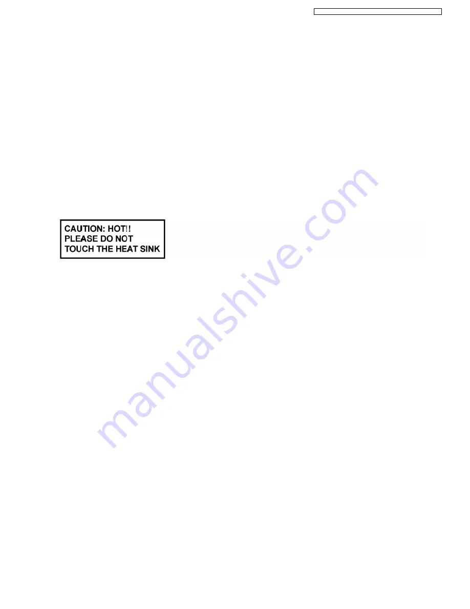
5. The Switch Regulator IC may have high temperature after prolonged use.
6. Use caution when removing the top cabinet and avoid touching heat sinks located in the unit.
7. Select items from the following index when checks or replacement are required.
•
•
•
•
Disassembly of Top Cabinet
•
•
•
•
Disassembly of DVD/CD Changer Mechanism Unit
•
•
•
•
Disassembly of DVD Module P.C.B.
•
•
•
•
Disassembly of USB Relay P.C.B.
•
•
•
•
Disassembly of Rear Panel
•
•
•
•
Disassembly of Main P.C.B.
•
•
•
•
Replacement of Regulator IC (IC2810)
•
•
•
•
Disassembly of Front Panel
•
•
•
•
Disassembly of Mic P.C.B.
•
•
•
•
Disassembly of Panel P.C.B.
•
•
•
•
Disassembly of Tact Swtich P.C.B.
•
•
•
•
Disassembly of USB P.C.B.
•
•
•
•
Replacement CD Lid
•
•
•
•
Disassembly of Deck Mechanism Unit
•
•
•
•
Replacement Cassette Lid
•
•
•
•
Disassembly of Deck P.C.B.
•
•
•
•
Disassembly of D-Amp P.C.B. & Speaker P.C.B.
•
•
•
•
Replacement of Digital Amp IC (IC5100)
•
•
•
•
Disassembly of SMPS P.C.B.
•
•
•
•
Replacement of Switch Regulator IC (IC5701)
•
•
•
•
Replacement of Regulator Diode (D5904/D5905)
•
•
•
•
Replacement of Regulator Diode (D5702)
•
•
•
•
Disassembly of Traverse Unit
•
•
•
•
Disassembly of Traverse Deck (DT69U3)
•
•
•
•
Disassembly of Deck Mechanism
•
•
•
•
Disassembly of Pinch Roller F Assembly & Head Block Unit
•
•
•
•
Disassembly of Disassembly of Capstan Motor Assembly, Capstan Belt A, Capstan Belt B & Winding Belt
47
SA-VK960GC / SA-VK960GCS / SA-VK960GCT / SA-VK960GS
Summary of Contents for SA-VK960GC
Page 13: ...Fig 5 2 13 SA VK960GC SA VK960GCS SA VK960GCT SA VK960GS ...
Page 50: ...10 2 Main Components and P C B Locations 50 SA VK960GC SA VK960GCS SA VK960GCT SA VK960GS ...
Page 84: ...84 SA VK960GC SA VK960GCS SA VK960GCT SA VK960GS ...
Page 86: ...SA VK960GC SA VK960GCS SA VK960GCT SA VK960GS 86 ...
Page 96: ...96 SA VK960GC SA VK960GCS SA VK960GCT SA VK960GS ...
Page 116: ...SA VK960GC SA VK960GCS SA VK960GCT SA VK960GS 116 ...
Page 124: ...SA VK960GC SA VK960GCS SA VK960GCT SA VK960GS 124 ...
Page 128: ...22 Exploded Views 128 SA VK960GC SA VK960GCS SA VK960GCT SA VK960GS ...
Page 129: ...22 1 Cabinet Parts Location SA VK960GC SA VK960GCS SA VK960GCT SA VK960GS 129 ...
Page 130: ...SA VK960GC SA VK960GCS SA VK960GCT SA VK960GS 130 ...
Page 132: ...SA VK960GC SA VK960GCS SA VK960GCT SA VK960GS 132 ...
Page 133: ...22 3 Packaging SF VK960 SA VK960GC SA VK960GCS SA VK960GCT SA VK960GS 133 ...


