43
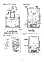
Step 5 Remove 2 screws.
Step 6 Detach 5P FFC at the connector (FP8252) on Backend
P.C.B. Ass’y.
Step 7 Detach 6P FFC at the connector (FP8251) on Backend
P.C.B. Ass’y.
Step 8 Detach 24P FFC at the connector (FP8531) on Backend
P.C.B. Ass’y.
Step 9 Remove DVD Mechanism Unit.
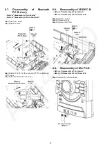
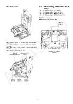
8.14. Disassembly of Backend P.C.B.
Ass’y
• Refer to “Disassembly of Top Cabinet”.
• Refer to “Disassembly of Front Panel Unit”.
• Refer to “Disassembly of Main P.C.B. Ass’y”.
• Refer to “Disassembly of DVD Mechanism Unit”.
Step 1 Remove 2 screws.
Step 2 Remove Backend P.C.B. Ass’y.
Summary of Contents for SA-VKX95EE
Page 5: ...5 1 4 Caution For AC Cord For GS only Figure 1 3 ...
Page 12: ...12 5 Location of Controls and Components 5 1 Remote Control Key Button Operation ...
Page 13: ...13 5 2 Main Unit Key Button Operation ...
Page 14: ...14 6 Service Mode 6 1 Service Mode Table ...
Page 15: ...15 6 2 Sales Demonstration Lock Function ...
Page 20: ...20 6 5 Self Diagnostic Mode 6 5 1 Self Diagnostic Mode Table 1 For DVD Module ...
Page 21: ...21 6 5 2 Self Diagnostic Mode Table 2 For DVD Module ...
Page 22: ...22 6 5 3 Self Diagnostic Mode Table 3 For DVD Module ...
Page 35: ...35 8 3 Main Components and P C B Locations ...
Page 46: ...46 ...
Page 58: ...58 ...
Page 60: ...60 ...
Page 86: ...86 ...
Page 96: ...96 ...
Page 100: ...100 ...

